Back to Contents
Specifications
Connectors
Controls and Lights
Physical
Environmental
System Setup Options
System Setup
Entering System Setup
System Setup Screens
Onboard Devices
System
Drives
LED Control
Performance
Power Management
Security
Time
Off Do not use the Auto Power Time
Maintenance
Post Behavior
Changing Boot Sequence for the Current Boot
Boot Sequence
Option Settings
Setup & Boot Menu default
¡ In Windows XP, click Start→ Turn Off Computer→ Turn off
Clearing Forgotten Passwords
Changing Boot Sequence for Future Boots
Computer, Keyboard, and Monitor
Clearing Cmos Settings
Cleaning Your Computer
Floppy Drive
FCC Notices U.S. Only
Mouse
CDs and DVDs
FCC Identification Information
Contacting Dell
Class B
Australia Sydney
Argentina Buenos Aires
Aruba
Technical Support 0011
Cayman Islands
Brunei
Canada North York, Ontario
Chile Santiago
Dominica
Czech Republic Prague
Denmark Copenhagen
Dominican Republic
Grenada
Germany Frankfurt
Greece
Guatemala
Business computers
Customer Service
Sales
Sales Ireland Cherrywood
Luxembourg
Korea Seoul
Latin America
Support.ap.dell.com
Norway Lysaker
New Zealand Support.ap.dell.com
Nicaragua
Panama
South Africa Johannesburg
Singapore Singapore
Slovakia Prague
09/091
Thailand
Customer Service Bracknell
Taiwan
Trinidad/Tobago
Virgin Islands
Financial Services
A. Austin, Texas
Venezuela
Find It Here
Support.dell.com
¡ In Windows XP, click Start and click Help and Support
Click Help and Support
Glossary
Device driver See driver
Docking device See APR
Page
Page
Module bay See media bay
NIC See network adapter
Page
Video resolution See resolution
Back to Contents
Preparing to Work Inside Your Computer
Before You Begin
Recommended Tools
Windows XP, click Start→ Turn Off Computer→ Turn off
Removing the Computer Cover
Inside View of Your Computer
System Board Components
Frntusb
Memory
DDR2 Memory Overview
Addressing Memory Configurations
Installing Memory
Cards
Removing Memory
Removing PCI and PCI Express Cards
Installing PCI and PCI Express Cards
Page
Page
Page
Page
Network Adapter and Sound Card Settings
Drives
About Serial ATA Drives
General Drive Installation Guidelines
Hard Drive
Removing a Hard Drive
Page
Installing a Hard Drive
Drive Panel
Removing the Drive Panel
Removing a Floppy Drive
Floppy Drive
Replacing the Drive Panel
Installing a Floppy Drive
Media Card Reader
Removing a Media Card Reader
Installing a Media Card Reader
Optical Drive
Removing an Optical Drive
Installing an Optical Drive
Removing the Liquid Cooling Assembly
Liquid Cooling Assembly
Safety Instructions for Liquid Cooling Assembly
Tecpump
Removing the Processor
Installing the Liquid Cooling Assembly
Processor
Installing the Processor
Fans
Removing the Card Fan
Installing the Card Fan
Removing the Optional Hard Drive Fan
Installing the Optional Hard Drive Fan
System Board
Removing the System Board
Installing the System Board
Power Supply
Power Supply PSU DC Connector Pin Assignments
DC Power Connector P1
KW Power Supply Pin Number Signal name AWG Wire Color
DC Power Connector P2
DC Power Connector P3 Graphics Card
DC Power Connector P6 and P7 BAY1 and Bay2
DC Power Connector P4 Graphics Card
DC Power Connector P5 FD1
DC Power Connectors P8 and P9 HDD0 and HDD1
DC Power Connector P15 Graphics Card 1-KW PSU Only
DC Power Connectors P10-P13 HDD2 and HDD5
DC Power Connectors P14 Peripheral
Pin Number Signal Name AWG Wire Color
Removing the Power Supply
DC Power Connector P16 Graphics Card 1-KW PSU Only
Installing the Power Supply
Removing the Front I/O Panel
Front I/O Panel
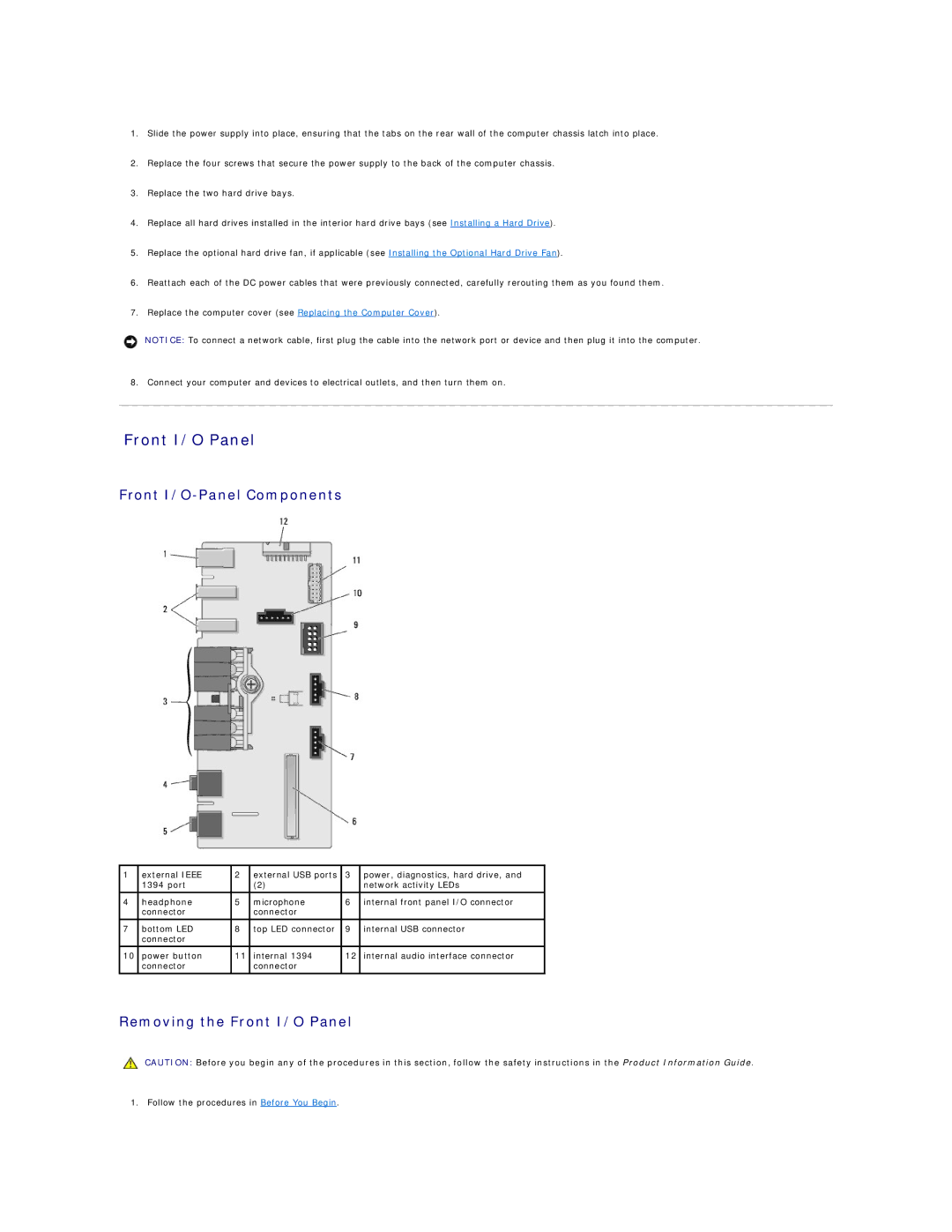
Front I/O-Panel Components
Installing the I/O Panel
Removing the Computer Stand
Battery
Replacing the Battery
Replacing the Computer Cover
Back to Contents
Understanding Dual-Graphics Technology
Understanding CPU Overclocking
Dell QuickSet
Front and Back View of the Computer
Front View
Back View
Front I/O Connectors
To ensure maximum system stability. Failure to install
Resulting in bodily injury or damage to the computer
Back I/O Connectors
Attaching the Computer Stand
RCA S/PDIF
Installing Your Computer in an Enclosure
Connecting Monitors
Connecting a Monitor Without an Adapter
Connecting a Monitor With an Adapter
Connecting a Monitor in a Dual Graphics Card Configuration
Connecting Two or More Monitors
Connecting a TV
About Your RAID Configuration
RAID Level 0 Configuration
RAID Level 5 Configuration
RAID Level 1 Configuration
RAID Level 0+1 Configuration
Using the Nvidia MediaShield ROM Utility
Configuring Your Hard Drives for RAID
Setting Your Computer to RAID-Enabled Mode
Click Create under System Tasks
Using Nvidia MediaShield
Creating a RAID Array
Clearing System Data window appears
Deleting a RAID Array
Free Disk Selection window appears
Using Multimedia
Rebuilding a RAID Configuration
How to Copy a CD, DVD, or BD
Copying CD, DVD, and Blu-ray Disc BD Media
Media Type Read Write Rewritable
Using Blank CD, DVD, and BD Media
Helpful Tips
Using a Media Card Reader Optional
MMC/RS-MMC
Transferring Information to a New Computer
Network Setup Wizard
Click Checklist for creating a network
Hibernate Mode
Power Management Options in Windows XP
Standby Mode
Advanced Tab
Power Options Properties
Power Schemes Tab
Hibernate Tab
Configuring Power Management Settings
Power Management Options in Windows Vista
Sleep Mode
Drive Problems
Solving Problems
Battery Problems
Click Start and click My Computer
Problems writing to an optical drive
Mail, Modem, and Internet Problems
Optical drive problems
Hard drive problems
Click Uninstall
Error Messages
Click Start → All Programs→ Modem Diagnostic Tool
Click Start→ All Programs→ Modem Helper
Ieee 1394 Device Problems
Keyboard Problems
Lockups and Software Problems
Other software problems
Memory Problems
Mouse Problems
Solid blue screen appears
Click Start→ Control Panel→ Mouse
Network Problems
Power Problems
Click Start → Control Panel→ Hardware and Sound→ Mouse
Click Start → Control Panel→ Hardware and Sound→ Printer
Printer Problems
Scanner Problems
Click Properties and click Ports
No sound from speakers
Sound and Speaker Problems
No sound from headphones
3D image quality is poor
Video and Monitor Problems
Screen is blank Screen is difficult to read
Click Start→ Control Panel→ Appearance and Themes
Problem Description Suggested Resolution
Power Lights
Diagnostic Lights
Beep Codes
Code Cause
System Messages
Message Possible Cause Corrective Action
Starting Dell Diagnostics From Your Hard Drive
Dell Diagnostics
When to Use Dell Diagnostics
Tab Function
Dell Diagnostics Main Menu
Option Function
Identifying Drivers
What Is a Driver?
Drivers
Click Start → Computer.→ System Properties→ Device Manager
Using the Drivers and Utilities Media
Manually Reinstalling Drivers
Restoring Your Operating System
Using Microsoft Windows System Restore
Starting System Restore
Enabling System Restore
Using Dell PC Restore and Dell Factory Image Restore
Undoing the Last System Restore
Windows XP Dell PC Restore
Windows Vista Dell Factory Image Restore
Select Repair Your Computer
Click Dell Factory Image Restore
Using the Operating System Media
Reinstalling Windows XP or Windows Vista
Before you Begin
Troubleshooting Software and Hardware Problems
Click Start and click Help and Support