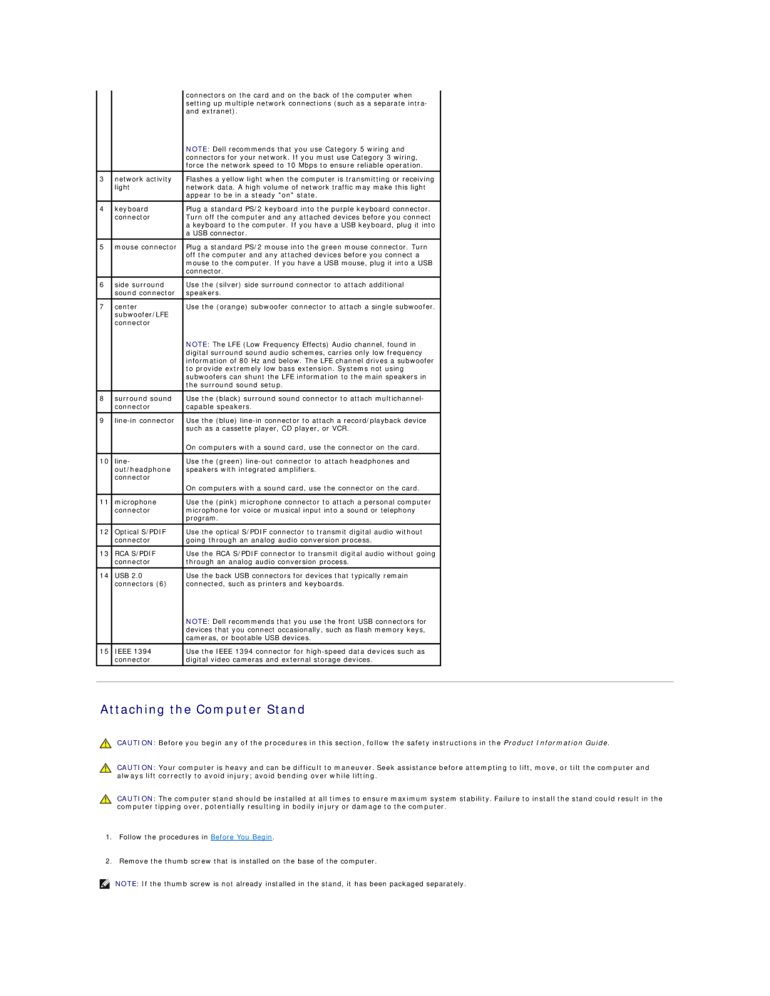
|
| connectors on the card and on the back of the computer when |
|
|
| setting up multiple network connections (such as a separate intra- |
|
|
| and extranet). |
|
|
| NOTE: Dell recommends that you use Category 5 wiring and |
|
|
| connectors for your network. If you must use Category 3 wiring, |
|
|
| force the network speed to 10 Mbps to ensure reliable operation. |
|
|
|
|
|
3 | network activity | Flashes a yellow light when the computer is transmitting or receiving |
|
| light | network data. A high volume of network traffic may make this light |
|
|
| appear to be in a steady "on" state. |
|
|
|
|
|
4 | keyboard | Plug a standard PS/2 keyboard into the purple keyboard connector. |
|
| connector | Turn off the computer and any attached devices before you connect |
|
|
| a keyboard to the computer. If you have a USB keyboard, plug it into |
|
|
| a USB connector. |
|
|
|
|
|
5 | mouse connector | Plug a standard PS/2 mouse into the green mouse connector. Turn |
|
|
| off the computer and any attached devices before you connect a |
|
|
| mouse to the computer. If you have a USB mouse, plug it into a USB |
|
|
| connector. |
|
|
|
|
|
6 | side surround | Use the (silver) side surround connector to attach additional |
|
| sound connector | speakers. |
|
7 | center | Use the (orange) subwoofer connector to attach a single subwoofer. |
|
| subwoofer/LFE |
|
|
| connector |
|
|
|
| NOTE: The LFE (Low Frequency Effects) Audio channel, found in |
|
|
| digital surround sound audio schemes, carries only low frequency |
|
|
| information of 80 Hz and below. The LFE channel drives a subwoofer |
|
|
| to provide extremely low bass extension. Systems not using |
|
|
| subwoofers can shunt the LFE information to the main speakers in |
|
|
| the surround sound setup. |
|
|
|
|
|
8 | surround sound | Use the (black) surround sound connector to attach multichannel- |
|
| connector | capable speakers. |
|
|
|
|
|
9 | Use the (blue) |
| |
|
| such as a cassette player, CD player, or VCR. |
|
|
| On computers with a sound card, use the connector on the card. |
|
|
|
|
|
10 | line- | Use the (green) |
|
| out/headphone | speakers with integrated amplifiers. |
|
| connector |
|
|
|
| On computers with a sound card, use the connector on the card. |
|
11 | microphone | Use the (pink) microphone connector to attach a personal computer |
|
| connector | microphone for voice or musical input into a sound or telephony |
|
|
| program. |
|
|
|
|
|
12 | Optical S/PDIF | Use the optical S/PDIF connector to transmit digital audio without |
|
| connector | going through an analog audio conversion process. |
|
13 | RCA S/PDIF | Use the RCA S/PDIF connector to transmit digital audio without going |
|
| connector | through an analog audio conversion process. |
|
14 | USB 2.0 | Use the back USB connectors for devices that typically remain |
|
| connectors (6) | connected, such as printers and keyboards. |
|
|
| NOTE: Dell recommends that you use the front USB connectors for |
|
|
| devices that you connect occasionally, such as flash memory keys, |
|
|
| cameras, or bootable USB devices. |
|
|
|
|
|
15 | IEEE 1394 | Use the IEEE 1394 connector for |
|
| connector | digital video cameras and external storage devices. |
|
|
|
|
|
|
|
|
|
Attaching the Computer Stand
CAUTION: Before you begin any of the procedures in this section, follow the safety instructions in the Product Information Guide.
CAUTION: Your computer is heavy and can be difficult to maneuver. Seek assistance before attempting to lift, move, or tilt the computer and always lift correctly to avoid injury; avoid bending over while lifting.
CAUTION: The computer stand should be installed at all times to ensure maximum system stability. Failure to install the stand could result in the computer tipping over, potentially resulting in bodily injury or damage to the computer.
1.Follow the procedures in Before You Begin.
2.Remove the thumb screw that is installed on the base of the computer.
NOTE: If the thumb screw is not already installed in the stand, it has been packaged separately.
