Reference and Troubleshooting Guide
Page
Safety Instructions
Page
Ergonomic Computing Habits
Viii
Protecting Against Electrostatic Discharge
When Removing or Installing Memory Modules
Page
About This Guide
Preface
Other Documents You May Need
Warranty and Return Policy Information
Notational Conventions
Example del c\myfile.doc
Typographical Conventions
No boot device available
Contents
Xvi
Getting Help
Installing System Software
Xviii
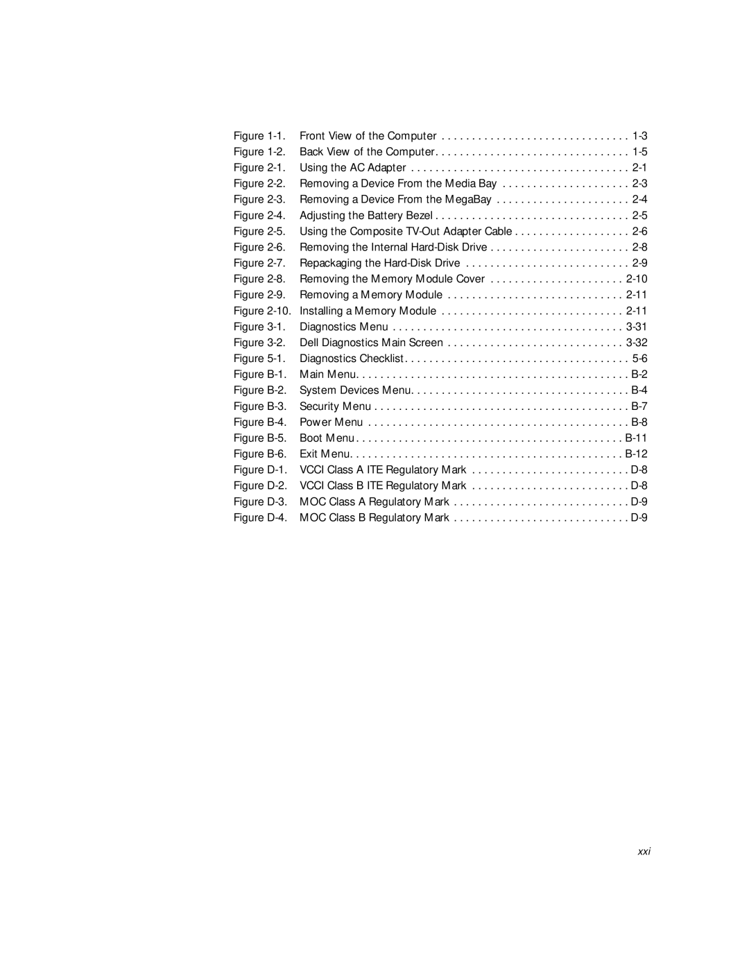
Figures
Index
Tables
Xxi
Xxii
Xxiii
Xxiv
Introduction
Hardware Features
Page
Front View of the Computer
Front View of the Computer
Page
Back View of the Computer
Back View of the Computer
Page
Available Options and Upgrades
Software Features
Getting Help
Using the AC Adapter
Options and Upgrades
Using the Media Bay
Removing a Device From the Media Bay
Using the MegaBay
Removing a Device From the MegaBay
Adjusting the Battery Bezel
Installing a Battery
Attaching the Composite TV-Out Adapter Cable
Using the Composite TV-Out Adapter Cable
Installing an Internal Hard-Disk Drive
Removing the Internal Hard-Disk Drive
Returning a Hard-Disk Drive to Dell
Installing Memory Modules
Removing the Memory Module Cover
Removing a Memory Module
Creating the Save-to-Disk Suspend File
Port Replicator
Connecting Other External Devices
Page
Checking the Basics
Basic Troubleshooting
Checking Connections
Environmental Factors
Power
Drives
Modem
Look and Listen
Cleaning Diskette Drives
Boot Routine Indications
Setup Options
Installing and Configuring Software
Finding Software Solutions
Start-Up Files
Using Software
Error Messages
Input Errors
Avoiding Interrupt Assignment Conflicts
Program Conflicts
Troubleshooting a Wet Computer
Troubleshooting Procedures
Support.dell.com Basic Troubleshooting
Troubleshooting a Damaged Computer
Troubleshooting a Power Failure
Total Power Failure When Using a Battery
Total Power Failure When Using the AC Adapter
Support.dell.com Basic Troubleshooting
No Power to a Part of the Computer
Troubleshooting the Diskette Drive
Troubleshooting the CD-ROM or DVD-ROM Drive
Troubleshooting the Hard-Disk Drive
Support.dell.com Basic Troubleshooting
Troubleshooting an External Keyboard
Troubleshooting Memory
Troubleshooting the Display
Troubleshooting an External Monitor
Page
Troubleshooting the Basic I/O Functions
Troubleshooting the Serial and Parallel Ports
Troubleshooting a Parallel Printer
Troubleshooting a Serial I/O Device
Troubleshooting the Infrared Port
Troubleshooting the Touch Pad
Troubleshooting Audio Functions
Running the Dell Diagnostics
Starting the Dell Diagnostics
Select Devices to Test
Dell Diagnostics Main Screen
Highlight Select Devices to Test in the Diagnostics Menu
Using the Dell Diagnostics
Menu
Test
Keys
Device Group
Device
Page
Installing the Windows 98 Operating System
Installing System Software
Select Start Windows 98 Setup from CD-ROM and press Enter
Installing the Audio Driver
Installing Drivers and Utilities for Windows
Installing the Touch Pad Driver
Installing the Video Driver
Installing the Internal Modem Driver Optional
At the Welcome Screen, click Next
Installing the Software DVD Decoder Optional
Installing Help From the CD
Installing the System Help
Click Dell Documents Technical Information
Downloading Help From the Support Web Site
Click Support Your Dell
Click Inspiron Notebooks
Creating the Save-to-Disk Suspend Partition
Installing Drivers and Utilities for Windows NT
Click OK in the Invalid Display Settings dialog box
Changing Video Resolution
Important Information window, click Next
Want to restart my computer now
Installing the Power Management Configuration Utility
Softex PC Card Controller Diagnostics window appears
Installing the PC Card Configuration Utility
Click I Understand
Installing the Internal Modem Driver Optional
Http//support.dell.com
Contacting Dell
Technical Assistance
Getting Help
World Wide Web
Help Tools
TechFax Service
AutoTech Service
TechConnect BBS
Technical Support Service
Problems With Your Order
Automated Order-Status System
Before You Call
Diagnostics Checklist
Diagnostics Checklist
1344
Dell Contact Numbers
International Dialing Codes
Austria
Australia
Belgium
China
Brunei
Canada
Chile
France
Czech Republic
Denmark
Finland
Hong Kong
Germany
Ireland
Latin America
Italy
Japan
Korea
Mexico
Luxembourg
Macau
Malaysia
Poland
Netherlands
New Zealand
Norway
Pacific Countries
Singapore
South Africa
Southeast Asian
Thailand
Sweden
Switzerland
Taiwan
Dell Home and Small Business Group
Table A-1. Technical Specifications
Technical Specifications
PC Card
Integrated Audio
Keyboard
AC Adapter
Environmental Computer
Using the Setup Program
Main Menu
Accessing the Setup Program
Main menu
Table B-1. Main Menu Options
System Devices menu
System Devices Menu
Set to Customized, the Mode is SIR and the Base I/O
Customized default, sets the Base I/O address/IRQ to
Base I/O address is 378, the Interrupt is IRQ 7,
Security menu
Security Menu
Set
Figure B-4. Power Menu
Power Menu
Minutes, 15 Minutes, 20 Minutes, 30 Minutes, 40 Min
Minute, 2 Minutes, 4 Minutes, 6 Minutes, 8 Minutes
Suspend Mode must be set to Save to RAM
CD-ROM/DVD
Boot Menu
CD-ROM/DVD
Exit Menu
Table B-6. Exit Menu Options
Page
System Messages
System Messages and Beep Codes
Run the Stuck Key Test in the PC-AT Compatible
Nnnn
Run the System Board Devices device group
Run Setup
Run the PC-AT Compatible Keyboards device group
System Beep Codes
Support.dell.com System Messages and Beep Codes C-5
Page
Regulatory Notices
FCC Notices U.S. Only
Modem Regulatory Information
Class a Class B
Fax Branding
IC Notice Canada Only
Support.dell.com Regulatory Notices D-5
CE Notice European Union
Battery Disposal
Vcci Notice Japan Only
EN 55022 Compliance Czech Republic Only
Class a ITE
Class B ITE
MOC Notice South Korea Only
Class B Device
Class a Device
Wymagania Polskiego Centrum Badañ i Certyfikacji
Polish Center for Testing and Certification Notice
Pozosta³e instrukcje bezpieczeñstwa
NOM Information Mexico Only
Información para NOM únicamente para México
Coverage During Year One
Limited Three-Year Warranty U.S. Only
General Provisions
Coverage During Years Two and Three
Limited Three-Year Warranty Canada Only
Coverage During Year One
Total Satisfaction Return Policy U.S. and Canada Only
Page
Additional Information
Macrovision Product Notice
Previous Products
Software
Page
Index
See also error messages about, C-4
Beep codes, C-4 error messages
NVRAM, B-1
Technical assistance obtaining
Troubleshooting water damage, 3-10 where to start
