iQ Series, Ultrasonic Hand Held Systems User’s Manual
Stack Assembly
Attaching a Replaceable Tip to a Horn
1.Inspect all horn and tip surfaces for stress cracks, chips, or gouges. Any of these irregularities will affect operation and could lead to further equipment damage. Contact the Dukane Ultrasonics Tooling Department concerning damaged horn components.
2.Apply an extremely thin layer of a high temperature, high pressure silicon grease to the back surface that mates with the horn. The grease will allow both surfaces to intimately mate and become acoustically transparent which improves the energy transfer. Do not apply any grease to the threads. We recommend
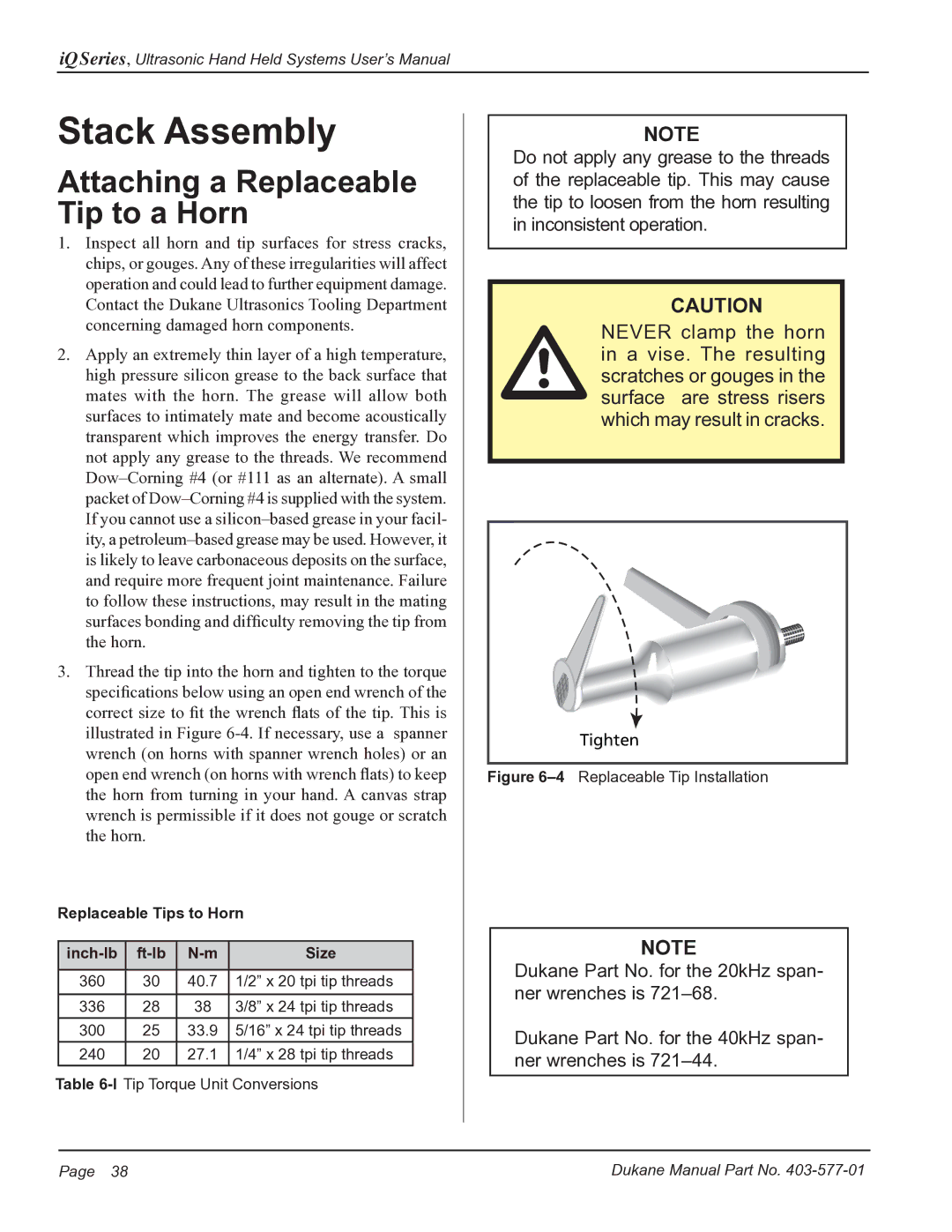
3.Thread the tip into the horn and tighten to the torque specifications below using an open end wrench of the correct size to fit the wrench flats of the tip. This is illustrated in Figure
Replaceable Tips to Horn
|
| Size | |
|
|
|
|
360 | 30 | 40.7 | 1/2” x 20 tpi tip threads |
|
|
|
|
336 | 28 | 38 | 3/8” x 24 tpi tip threads |
|
|
|
|
300 | 25 | 33.9 | 5/16” x 24 tpi tip threads |
|
|
|
|
240 | 20 | 27.1 | 1/4” x 28 tpi tip threads |
|
|
|
|
Table
NOTE
Do not apply any grease to the threads of the replaceable tip. This may cause the tip to loosen from the horn resulting in inconsistent operation.
CAUTION
NEVER clamp the horn in a vise. The resulting scratches or gouges in the surface are stress risers which may result in cracks.
Tighten
Figure 6–4 Replaceable Tip Installation
NOTE
Dukane Part No. for the 20kHz span- ner wrenches is
Dukane Part No. for the 40kHz span- ner wrenches is
Page 38 | Dukane Manual Part No. |