iQ Series, Ultrasonic Hand Held Systems User’s Manual
Connecting Cables - Quick Start Guide
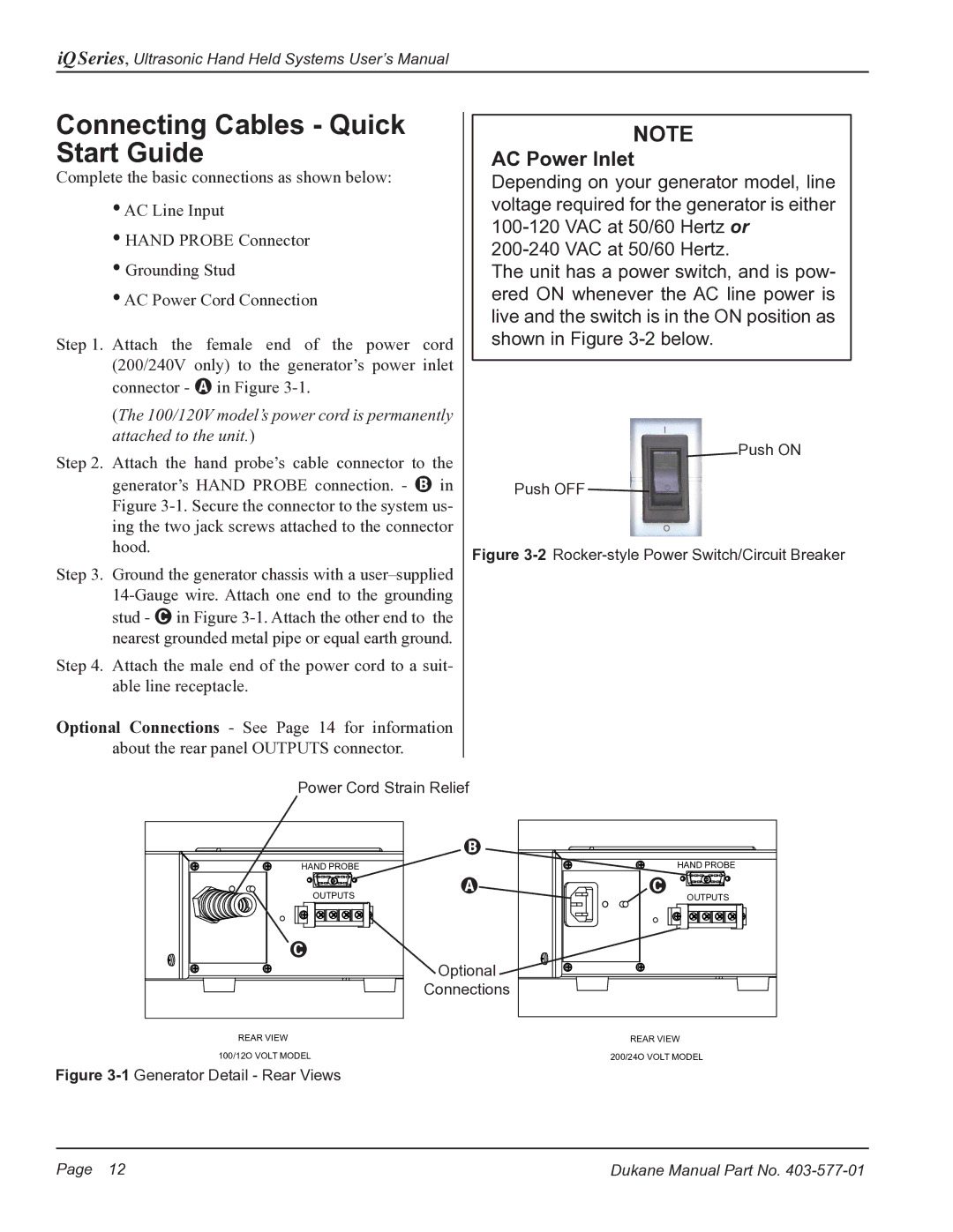
Complete the basic connections as shown below:
•AC Line Input
•HAND PROBE Connector
•Grounding Stud
•AC Power Cord Connection
Step 1. Attach the female end of the power cord (200/240V only) to the generator’s power inlet connector - A in Figure
(The 100/120V model’s power cord is permanently attached to the unit.)
Step 2. Attach the hand probe’s cable connector to the generator’s HAND PROBE connection. - B in Figure
Step 3. Ground the generator chassis with a
Step 4. Attach the male end of the power cord to a suit- able line receptacle.
Optional Connections - See Page 14 for information about the rear panel OUTPUTS connector.
NOTE
AC Power Inlet
Depending on your generator model, line voltage required for the generator is either
The unit has a power switch, and is pow- ered ON whenever the AC line power is live and the switch is in the ON position as shown in Figure
![]() Push ON
Push ON
Push OFF ![]()
Figure 3-2 Rocker-style Power Switch/Circuit Breaker
Power Cord Strain Relief
| B |
HAND PROBE |
|
OUTPUTS | A |
| |
C |
|
| Optional |
| Connections |
HAND PROBE |
C |
OUTPUTS |
REAR VIEW | REAR VIEW |
100/12O VOLT MODEL | 200/24O VOLT MODEL |
Figure 3-1 Generator Detail - Rear Views
Page 12 | Dukane Manual Part No. |