iQ Series, Ultrasonic Hand Held Systems User’s Manual
Attaching The Horn to a Booster, Booster to a Probe, or Horn to a Probe
1.Inspect all surfaces to be joined for stress cracks, chips, or gouges. Any of these irregularities will affect operation and could lead to further equipment damage. Contact the Dukane Ultrasonic Tooling Department concerning a damaged booster.
2.Ensure that the mating surfaces of the two components are clean and smooth. These surfaces must make inti- mate contact for the mechanical energy to pass from one component to the next. Pitting or a buildup of old grease and dirt on a mating surface will interfere with the energy transfer and reduce the power delivered.
3.Make sure that the stud in the horn or booster is tight. See the preceding mounting stud assembly instructions for torque specifications.
4.Remove any foreign matter from the threaded stud and mating hole.
5.Apply an extremely thin layer of a high temperature, high pressure silicon grease to the surface that mates with the horn. The grease will allow both surfaces to intimately mate and become acoustically transparent which improves the energy transfer. We recommend
NOTE
Always remove a probe stack from the machine in which it is mounted before attaching or removing a horn.
CAUTION
Never leave a horn or booster assembly hand tight. Torque it to the proper specifications before proceeding. If the as- sembly is installed without being properly torqued down, the assembly may vibrate severely, damaging the mat- ing surfaces and causing the generator to overload.
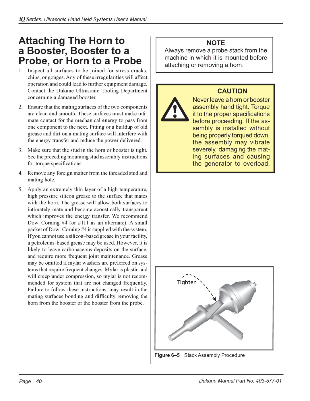
Tighten
Figure 6–5 Stack Assembly Procedure
Page 40 | Dukane Manual Part No. |