PowerH SERIES
HIGH | LOW | Address | ||
0 |
| 0 | ||
|
|
|
|
|
0 | 1... | F | 1... | 15 |
|
|
|
|
|
1 | 0... | F | 16... | 31 |
|
|
|
|
|
2 | 0... | F | 32... | 47 |
|
|
|
|
|
3 | 0... | F | 48... | 63 |
|
|
|
|
|
4 | 0... | F | 64... | 79 |
|
|
|
|
|
5 | 0... | F | 80... | 95 |
|
|
|
|
|
6 | 0... | F | 96... | 111 |
|
|
|
|
|
7 | 0... | F | 112... | 127 |
|
|
|
|
|
8 | 0... | F | 128... | 143 |
|
|
|
|
|
9 | 0... | F | 144... | 159 |
|
|
|
|
|
A | 0... | F | 160... | 175 |
|
|
|
|
|
B | 0... | F | 176... | 191 |
|
|
|
|
|
C | 0... | F | 192... | 207 |
|
|
|
|
|
D | 0... | F | 208... | 223 |
|
|
|
|
|
E | 0... | F | 224... | 239 |
|
|
|
|
|
F | 0... | A | 240... | 250 |
|
|
|
| |
F | B... | F | reserved | |
|
|
|
|
|
Table 4.3: CAN addresses
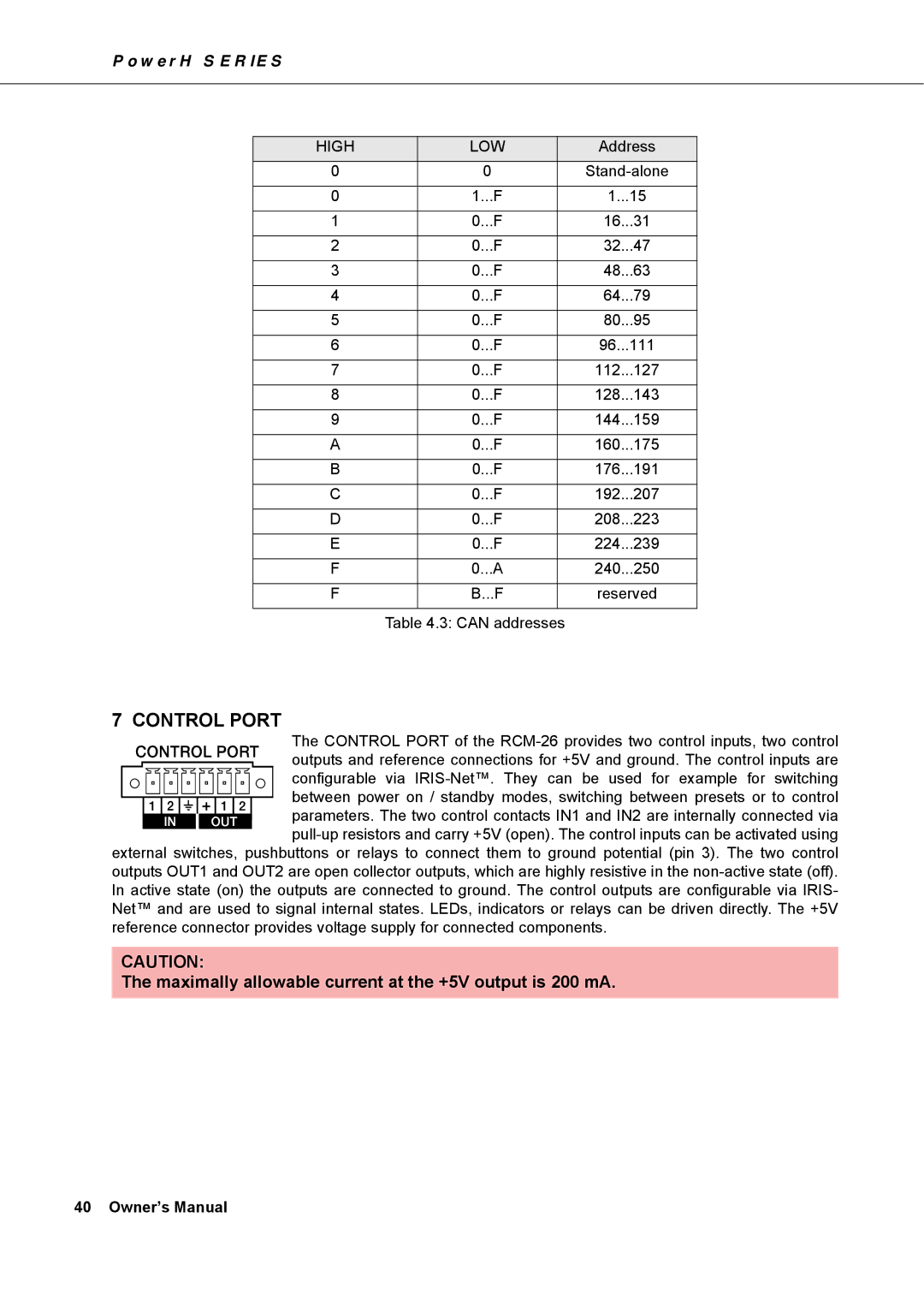
7 CONTROL PORT
The CONTROL PORT of the
between power on / standby modes, switching between presets or to control
![]()
![]() parameters. The two control contacts IN1 and IN2 are internally connected via
parameters. The two control contacts IN1 and IN2 are internally connected via
outputs OUT1 and OUT2 are open collector outputs, which are highly resistive in the
CAUTION:
The maximally allowable current at the +5V output is 200 mA.
40 Owner’s Manual