PowerH SERIES
3.6 Protections
In case one of the power amp’s internal protections responds during operation, a corresponding message appears on the LC display (or the
True RMS Mains Voltage and Current Measurement
PowerH SERIES amplifiers are consistently informed about the state of the mains network that they are connected to. The CPU of the power amplifier continually computes the current RMS (Root Mean Square, effective value) of the mains voltage and the mains current consumption. This genuine RMS measurement has substantial advantages over the commonly used peak value measurement:
•Mains voltage measurement functions reliably even with
•Mains voltage measurement is insusceptible to transient mains interference, as can occur when swit- ching inductive loads such as large electric motors.
•True mains current RMS measurement allows the precise matching of the power consumption to the characteristics of a mains circuit breaker. Detailed information about the adjustable Mains Circuit Brea- ker Protection function is provided in the following paragraph.
RMS measurement permanently protects the power amplifier against mains over or undervoltage. At the occurrence of extreme mains overvoltage, the power amp switches off to prevent severe damage. Switching on the power amp is not possible whenever mains overvoltage has been detected. The mains voltage monitoring protection switches the power amplifier off at the occurrence of extreme mains undervoltage (less than 70 V AC). In both cases, the blinking
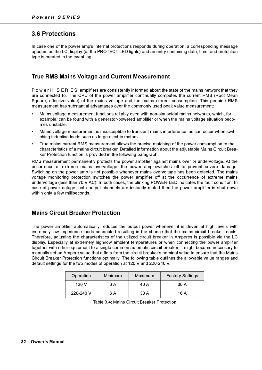
Mains Circuit Breaker Protection
The power amplifier automatically reduces the output power whenever it is driven at high levels with extremely
Operation |
| Minimum | Maximum | Factory Settings |
|
|
|
|
|
120 V |
| 6 A | 40 A | 30 A |
|
|
|
|
|
| 6 A | 30 A | 16 A | |
|
|
|
|
|
| Table 3.4: Mains Circuit Breaker Protection | |||
32 Owner’s Manual