ATCA-S201
Contact Address
Contents
NEW System Configuration
RAID Volume Configuration
NFS/SMB Share Setup Tools
RTM-ATCA-SXXX Installation
List of Figures
List of Tables
114
Safety Summary
Preface
Safety Statement
Flammability
EMI Caution
CE Notice European Community
Preface
About This Manual
How this manual is organized
Conventions Used in This Manual
Part Number Description
6806800H62B ATCA‐S201 Installation and Use Guide
Ctrl
Hardware Preparation and Installation
Antistatic Precautions
Unpacking Instructions
Features of the Atca Storage Module
ATCA-S201 Overview
Power Module
I/O Picmg standards compliance
Chassis I/O connections
X1 SAS
Zone 1, power backplane connections
Zone 3, Advanced RTM connector
AMC card connections
Zone 2, backplane connections
Ethernet Management port
LEDs
Front view- fully populated ATCA-S201 showing panel LEDs
Software driver support
Part Number, Serial Number, and Address Labels
Label Description
LED functional description
ATCA-S201 Diagram Showing Identification Label Location
ATCA-S201 Installation
Installation and removal of the Atca carrier blade
Important information about your chassis
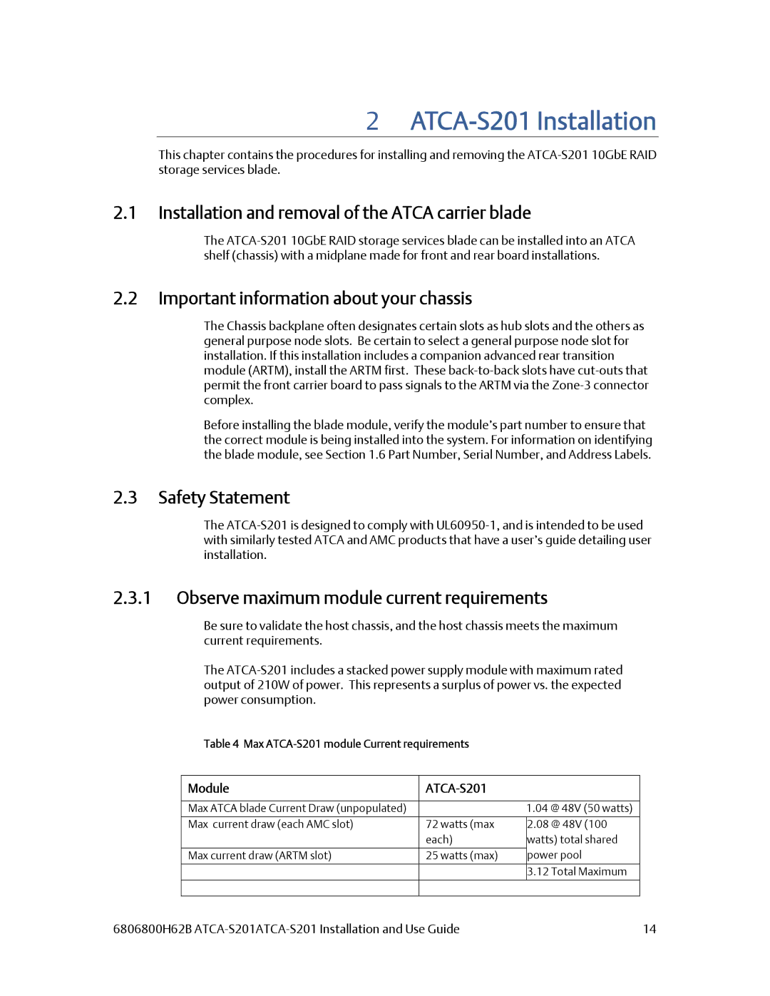
Observe maximum module current requirements
Before you install or Remove the Atca carrier blade
Observe ESD Precautions
Watch for Bent Pins or Other Damage
Use Caution When installing or removing the Atca carrier
Connector Mechanical keying
Installing the Atca carrier blade
Understand Hot Swap
Verify Slot Usage
Injector / Ejector latch and locking screw
Verifying the Hardware Installation
Removing the Atca carrier blade
To Verify the Hardware Installation
Configuration Step
New System
System boot overview
RS232 Console port
Flash boot device contents
UImage
Default blade login accounts and passwords
Password change procedure
Password recovery procedure
User account Default Description Password
Factory reset
Configuring a new ATCA-S201 blade
Serial ports
Ethernet ports
Management Configuration via Html browser
Management configuration via secure shell SSH
Management configuration via serial console shell
Command line configuration tool
Change IP address of any Ethernet resource
Perform manual Interactive changes
6806800H62B ATCA‐S201 Installation and Use Guide
Shell, configuration scripting options
Change Network Settings?
New system configuration, No Dhcp server
Example #2 Additional references
Boot console tool
Essential U-boot user commands
Boot command syntax Description
Essential U-boot configuration commands
Boot environment variables
Uboot= run flashboot
Boot environment variables shown with printenv
Bootfile
Manually assign management IP addresses
Network boot procedure
Uboot= saveenv
Network configuration
IP host
Enable Html browser access
Html login screen
CLI command syntax
Html Security certificates https
Web GUI command
CLI command syntax, single session management override
Auto logout inactivity period
Single session management override
Essential System Configuration Steps
Html tool, startup screen
Emerson ATCA-S201 Maintenance Network
System Identification and Time Zone attributes
CLI command syntax, set network property hostname
CLI command syntax, set network property domain name
Hostname
Domain Name
CLI command syntax, set network property system date
CLI command syntax, set network property system time
CLI command syntax, set network property system time zone
Time
CLI command syntax, set network property assign Name server
Name Server list
NTP Server list
World Menu item Daylight savings Menu Item Zone
CLI command syntax, set network property assign NTP server
Network time protocol NTP On/Off
Ethernet network port identification
Enable online/offline
Dhcp
IP address
Network Subnet mask
Broadcast
Gateway
MTU size
MAC address
Vlan Virtual Local Area Network support
Example #1 add a vlan interface to Xaui port 4, ID
Viewing active Vlan
Example #2 Remove vlan interfaces on Xaui port 4, ID
Example #2 list vlan interfaces on Xaui port 4, ID
# vi /etc/network.conf Example remove these 12 lines
Link aggregation and bonding
Link aggregation 802.3ad bonding, theory of operation
Bonding, CLI command syntax
Create new bond
Blade 1 Primary Configuration
Shelf communications
Shelf Address
192.68.100.32 127.0.0.1
Blade 1 Configuration IPMB-Address Hex for ATCA-S201
Shelf configuration menu parameters
10 I/O Status attributes
StorBlade99 ATCA-S201 IO Status
Blade maintenance, miscellaneous operations
StorBlade99 ATCA-S201 Maintenance
Blade, I/O Status indication
Software Reset SAS Controller
Reset I/O Status counters
Rescan SAS Topology, disk refresh
Html tool, Emerson ATCA-S201 MaintenanceCPU Status
CPU Status attributes
Html tool, Emerson ATCA-S201 MaintenanceATCA Status
Atca Status attributes
Button usage
Atca status indication
Svid
Ssid
Atcablade getstatus 2 +
Hardware RAID configuration
Jbod mode
Hardware RAID configuration Menu usage
CLI command syntax, setraid Add RAID configuration
Parameter Description
RAID1/E
RAID0
Important considerations and volume restrictions
Hardware RAID levels and capabilities
How new RAID definitions alter device menu display
Modify existing RAID configurations
Section
Hardware RAID Description Configuration
Understanding the Hardware RAID status table
Wwid
Software RAID configuration
Software RAID web-configuration menu usage
Parameter
RAID0 RAID1 RAID4 RAID5 RAID6
Software RAID, CLI command syntax
CLI command syntax, mdadm manage RAID configuration
Remove volume
Description Data Layout Diagram Level
Software RAID levels and capabilities
Benefits of a logical Volume Group /dev/vga
Benefits of a Logical device/disk /dev/vga/lva0
Viewing Physical disks
Interpreting physical disk status
Emerson ATCA-S201 Physical Disks
View physical disk properties
Disk view refresh, Re-draw Tree button
Create a logical Volume Group /dev/vga
Emerson ATCA-S201 LVM2 LVM2 Configuration
Follow these instructions to create a new volume group
Html tool, Emerson ATCA-S201 LVM2 Configuration
CLI command syntax, create new volume groups
Atcablade setlvm2 Y Ydisk Ndisk Y Y +
CLI command syntax, create new logical device
Creating a Logical Device /dev/vga/lva0
Extend/Expand a Logical Device /dev/vga/lva0
Follow these instructions to create a new logical device
Delete a Logical device /dev/vga/lva0
Manage shares prepare logical device for service
Commit a logical drive for iSCSI service
Block
File
Commit a logical drive for NAS service
Follow these instructions to assign iSCSI service
Follow these instructions to assign NAS service
CLI command syntax, create iSCSI share
CLI command syntax, format a logical volume
Un-commit an iSCSI share
Emerson ATCA-S201 Shares Manage Shares
Un-commit an NFS/SMB share
Follow these instructions to un-commit a logical drive
Mnt/shr/block/lva0 /mnt/shr/block/lva0
StorBlade99 ATCA-S201 Shared Resource /dev/vga/lva0
Re-name iSCSI shares, make more ‘human-friendly’
ISCSI device setup tools
ISCSI configuration menu
Emerson ATCA-S201 iSCSI iSCSI Configuration
Add or create an iSCSI target
Add or create an iSCSI LUN
Follow these instructions to create a new iSCSI target
Click the ‘add an iSCSI Target’ button
Target iqn.1995-07.com.emersonATCA-S201.Target0
LUNs Served By This Target
Lva0 ˇ
Fol
Remove an individual iSCSI LUN
Delete an iSCSI Target and all Luns
Follow these instructions to delete an iSCSI LUN
Follow these instructions to delete an iSCSI Target
Advanced iSCSI configuration expert mode
Sample ietd.conf file for iSCSI targets
6806800H62B ATCA‐S201 Installation and Use Guide
IncomingUser username password
Default
#Wthreads value
ISCSI Discovery filter configuration expert mode
Etc/initiators.allow Etc/initiators.deny
NFS/SMB Share setup tools
NFS and SMB mount point configuration menus
Nfs export /export/nfs/lvb0 Update
Rw,sync,nowdelay,rootsquash
Export an nfs or smb share
Nfs menu
Services, such Microsoft Windows
CLI command syntax, create nfs share
Emerson ATCA-S201 smb smb Configuration
Smb menu
CLI command syntax, create smb share
Remove an individual file-share Export
Follow these instructions to Delete a file-share export
Advanced file share configuration expert mode
Sample smb.conf file for samba/CIFs file shares
Sample /etc/export file for nfs file shares
Export option syntax
Exporthost1options hostNoptions
Common nfs export option definitions
Blade Maintenance Firmware upgrades
Blade Maintenance
Backup your blade configuration
Export System configuration file using web-GUI tool
Import restore a blade configuration
Export system configuration file using CLI
Import System configuration using web-GUI tool
Import System configuration using CLI
Normal Firmware Update procedures
Web flash tool, update procedure details
Download New Firmware package
File Description
Upgrade firmware procedure
StorBlade99 ATCA-S201 System Maintenance
Backup/nvdisk.tar.gz
Follow these instructions to load new firmware
Flashupdate.sh tool usage and options
Sbflash -r -k -u -t tftpserverIP
CLI flash tool, update procedure details
6806800H62B ATCA‐S201 Installation and Use Guide 100
Emergency firmware recovery, theory of operation
Jumper Settings
6806800H62B ATCA‐S201 Installation and Use Guide 101
JP1, jumper for primary/recovery Flash selection
Emergency flash recovery factory reset
6806800H62B ATCA‐S201 Installation and Use Guide 102
DDR2 Dimm
SAS
Clear root password
root password reset procedure method
6806800H62B ATCA‐S201 Installation and Use Guide 103
Tftpboot
6806800H62B ATCA‐S201 Installation and Use Guide 104
# reboot
Specifications for the ATCA-S201
Physical dimensions
Power Requirements
Environmental Specifications and Compliance
Environmental specifications for the ATCA-S201
Specification Value
Nebs Compliance
Electromagnetic Compliance
Connectors and Pin assignments
6806800H62B ATCA‐S201 Installation and Use Guide 107
EMC Emission compliancy
6806800H62B ATCA‐S201 Installation and Use Guide 108
AMC Module Slots
6806800H62B ATCA‐S201 Installation and Use Guide 109
AMC.3 PCI Express
CLK1 Clock AMC-AMC CLK2 CLK3
Extended
Zone 1 Connectors
6806800H62B ATCA‐S201 Installation and Use Guide 110
Zone 2 Connectors
6806800H62B ATCA‐S201 Installation and Use Guide 111
Zone 3 Connectors
6806800H62B ATCA‐S201 Installation and Use Guide 112
Connector J23, Zone-2 Signal Descriptions
6806800H62B ATCA‐S201 Installation and Use Guide 113
6806800H62B ATCA‐S201 Installation and Use Guide 114
Connector J33, PCIe and Miscellaneous RTM Pin Assignments
Row# Interface
6806800H62B ATCA‐S201 Installation and Use Guide 115
Fclka PCIRST# RTM# PCICFG#
6806800H62B ATCA‐S201 Installation and Use Guide 116
Connector J30, RTM Power Pin Signal Descriptions
Ipmi Ipmiscll Ipmisdal
Ipmiscll Ipmisdal 12VPP
Power Supply Mezzanine Module
6806800H62B ATCA‐S201 Installation and Use Guide 117
Sodimm DDR Module
CCL
Features of the Advanced Rear Transition Module
Overview
11.2 I/O Picmg Standards Compliance
11.3 I/O Interfaces
External SAS Connector
Ethernet Management Port RJ-45
10BRTM‐ATCA‐SXXX Overview
6806800H62B ATCA‐S201 Installation and Use Guide 120
Serial Console Port RJ-45
LEDs On RTM Faceplate
6806800H62B ATCA‐S201 Installation and Use Guide 121
Software Support
Products Supported by this Manual
Identification Labels
6806800H62B ATCA‐S201 Installation and Use Guide 122
RTM-ATCA-SXXX Identification Labels
6806800H62B ATCA‐S201 Installation and Use Guide 123
RTM-ATCA-SXXX Diagram Showing Identification Label Locations
Installation
Installation and Removal of the Rear Transition Module
Module Current
No Disk
Before You Install Or Remove The RTM
Two disk version No Disk
OFF State Less than Less than 0.4 W
Use Caution When Installing or Removing RTM
Installing the Advanced Rear Transition Module
RTM‐ATCA‐SXXX Installation
6806800H62B ATCA‐S201 Installation and Use Guide 126
6806800H62B ATCA‐S201 Installation and Use Guide 127
6806800H62B ATCA‐S201 Installation and Use Guide 128
Removing the Advanced Rear Transition Module
Mechanical and Connector Information
Specifications for the RTM-ATCA-SXXX
Module Current ATCA-S201-0 No Disk
ATCA-S201-2 Two disk version
RTM-ATCA-SXXX Mechanical and Connector Information
6806800H62B ATCA‐S201 Installation and Use Guide 131
RTM‐ATCA‐SXXX Mechanical and Connector Information
SAS Connector Port
RTM‐ATCA‐SXXX Mechanical and Connector Information
6806800H62B ATCA‐S201 Installation and Use Guide 132
6806800H62B ATCA‐S201 Installation and Use Guide 133
RTM-ATCA-SXXX Front Panel SAS Connector Pin Assignments
10/100/1000 Management Port Connector Pin Assignments
13.2.2 10/100/1000 Mb Management Port
6806800H62B ATCA‐S201 Installation and Use Guide 134
Serial Console Management Port Connector Pin Assignments
Serial Console Management Port
RTS GND DTR RXD TXD DSR CTS
6806800H62B ATCA‐S201 Installation and Use Guide 135
Connector P32, Management Infrastructure Pin Assignments
6806800H62B ATCA‐S201 Installation and Use Guide 136
Connector J33, Miscellaneous RTM Pin Assignments
6806800H62B ATCA‐S201 Installation and Use Guide 137
Connector J33, Miscellaneous RTM Signal Descriptions
J30, RTM Power Pin Header Assignment
6806800H62B ATCA‐S201 Installation and Use Guide 138
Ipmi Functions List
Ipmi and Management Controller Ipmc
Sensor data records
Sensor
ID String
ATCA-S201 Sensor Data Records
UNR UNC LNC LNR
6806800H62B ATCA‐S201 Installation and Use Guide 14‐2
RTM e-Keying Port Assignments
Ipmi Functions List
RTM-ATCA-SXXX Example FRU Data Records
Supported Ipmi Commands
6806800H62B ATCA‐S201 Installation and Use Guide 14‐3
SAS2
SAS3
6806800H62B ATCA‐S201 Installation and Use Guide 14‐4
Supported Ipmi Commands
Atca Commands
Ipmc Firmware Upgrade Procedure
Ipmitool utility
Ipmc Firmware Upgrade Procedure
6806800H62B ATCA‐S201 Installation and Use Guide 15‐2
Index
NFS
RAID
6806800H62B ATCA‐S201 Installation and Use Guide 16‐4
Index
Vlan