48
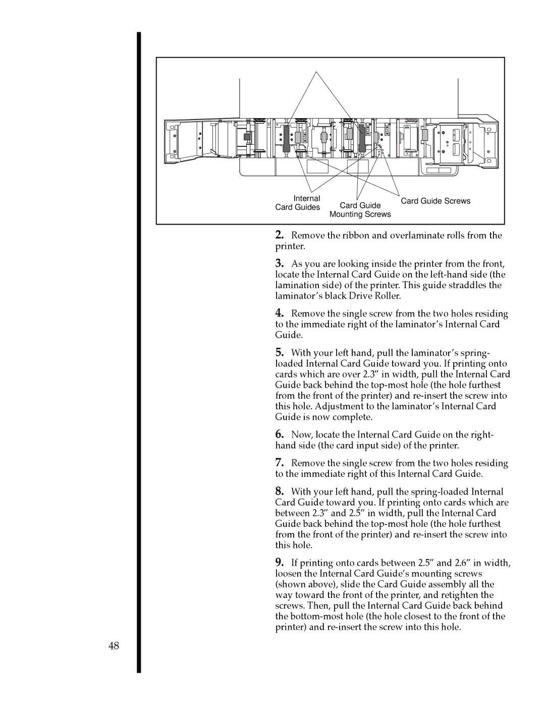
Internal | Card Guide | Card Guide Screws | |
Card Guides | |||
| |||
| Mounting Screws |
|
2.Remove the ribbon and overlaminate rolls from the printer.
3.As you are looking inside the printer from the front, locate the Internal Card Guide on the
4.Remove the single screw from the two holes residing to the immediate right of the laminatorÕs Internal Card Guide.
5.With your left hand, pull the laminatorÕs spring-
loaded Internal Card Guide toward you. If printing onto cards which are over 2.3Ó in width, pull the Internal Card Guide back behind the
6.Now, locate the Internal Card Guide on the right- hand side (the card input side) of the printer.
7.Remove the single screw from the two holes residing to the immediate right of this Internal Card Guide.
8.With your left hand, pull the
9.If printing onto cards between 2.5Ó and 2.6Ó in width, loosen the Internal Card GuideÕs mounting screws (shown above), slide the Card Guide assembly all the way toward the front of the printer, and retighten the screws. Then, pull the Internal Card Guide back behind the