4. INSTALLING OPTIONAL EQUIPMENT
|
| |
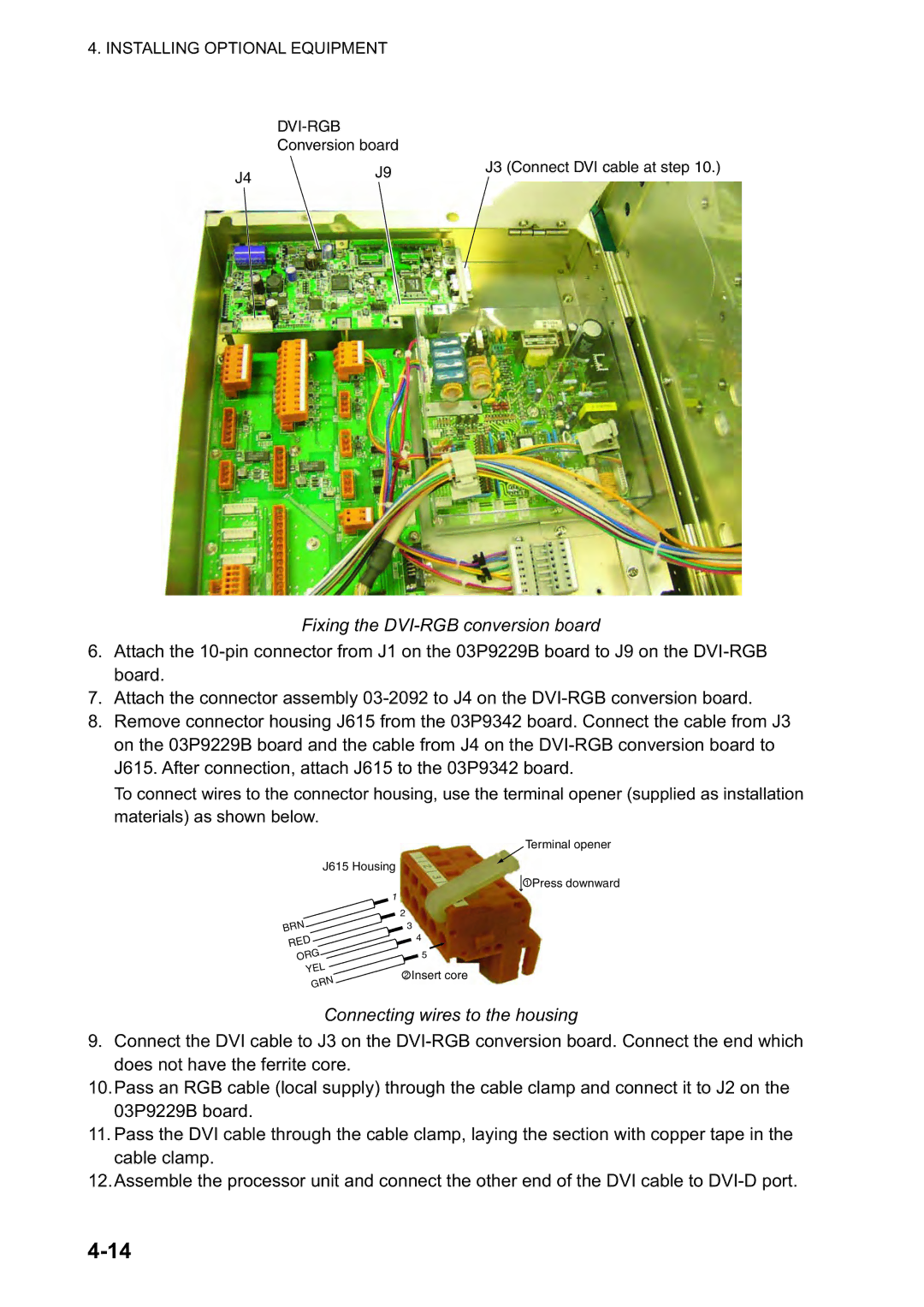
| Conversion board |
|
J4 | J9 | J3 (Connect DVI cable at step 10.) |
| ||
|
|
Fixing the DVI-RGB conversion board
6.Attach the
7.Attach the connector assembly
8.Remove connector housing J615 from the 03P9342 board. Connect the cable from J3 on the 03P9229B board and the cable from J4 on the
To connect wires to the connector housing, use the terminal opener (supplied as installation materials) as shown below.
Terminal opener
J615 Housing
1 Press downward
1
BRN ![]() RED ORG YEL GRN
RED ORG YEL GRN
2
3
4
![]() 5
5
2Insert core
Connecting wires to the housing
9.Connect the DVI cable to J3 on the
10.Pass an RGB cable (local supply) through the cable clamp and connect it to J2 on the 03P9229B board.
11.Pass the DVI cable through the cable clamp, laying the section with copper tape in the cable clamp.
12.Assemble the processor unit and connect the other end of the DVI cable to