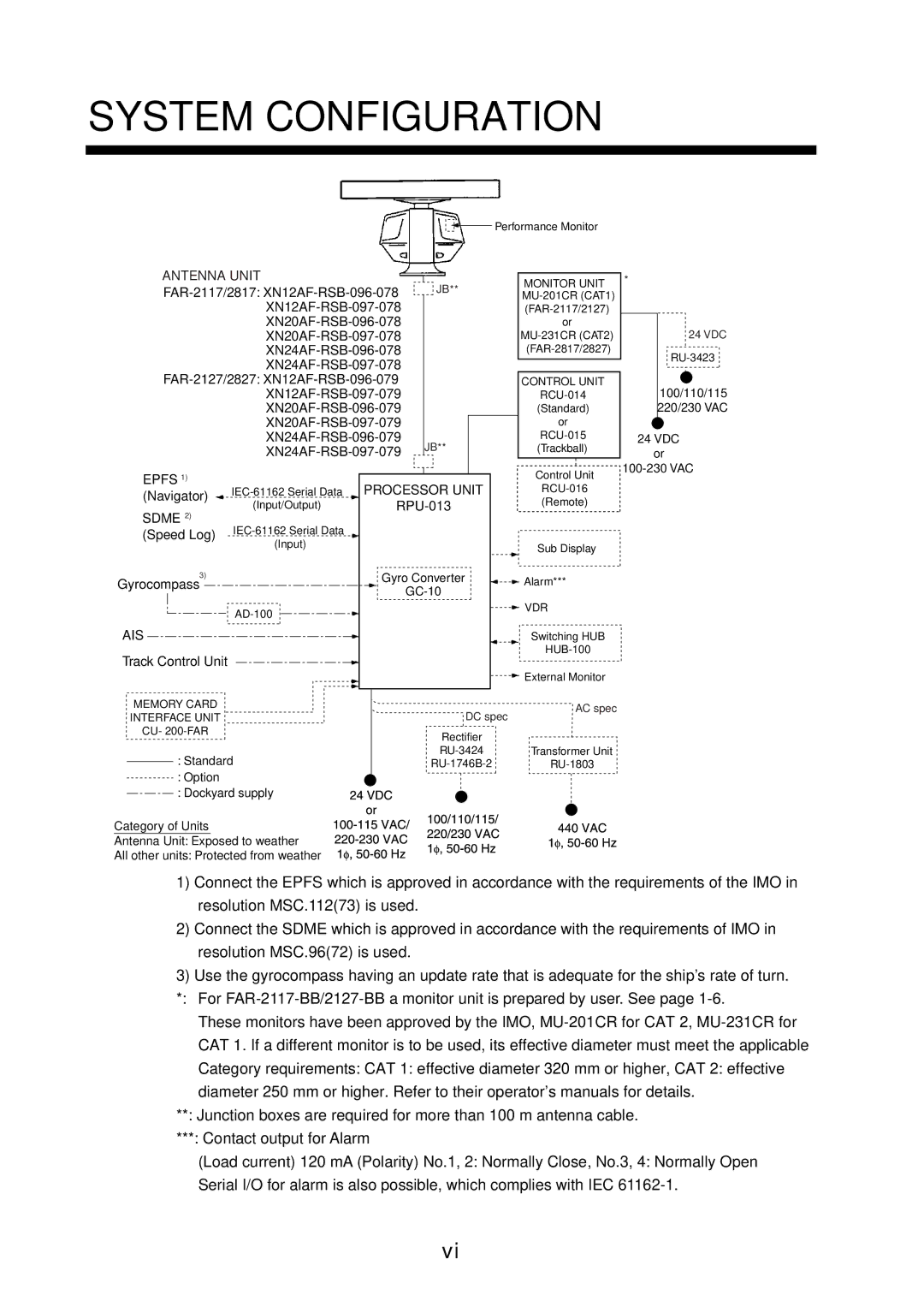
SYSTEM CONFIGURATION
![]()
![]() Performance Monitor
Performance Monitor
| ANTENNA UNIT |
|
|
| JB** | MONITOR UNIT | ||||
|
|
|
| |||||||
|
| |||||||||
|
| |||||||||
|
| |||||||||
|
|
|
|
|
|
| ||||
|
|
|
|
|
|
| or | |||
|
|
|
|
|
|
| ||||
|
|
|
|
|
|
| ||||
|
|
|
|
|
|
|
| |||
|
|
|
|
| CONTROL UNIT | |||||
|
|
|
|
|
|
| ||||
|
|
|
|
|
|
| (Standard) | |||
|
|
|
|
|
|
| or | |||
|
|
|
| JB** |
|
| ||||
|
|
|
|
| (Trackball) | |||||
|
|
|
|
|
|
|
| |||
| EPFS 1) |
|
|
|
|
|
|
| Control Unit | |
|
|
|
|
|
|
|
| |||
| PROCESSOR UNIT |
| ||||||||
| (Navigator) |
| ||||||||
| (Input/Output) |
|
| (Remote) | ||||||
| SDME 2) |
|
| |||||||
|
|
|
|
|
|
|
|
| ||
| (Speed Log) |
|
|
|
|
|
|
| ||
|
|
| (Input) |
|
|
|
|
|
| Sub Display |
|
|
|
|
|
|
|
|
|
| |
3) |
|
| Gyro Converter |
| Alarm*** | |||||
Gyrocompass |
|
|
| |||||||
|
|
|
| |||||||
|
|
|
|
|
|
|
| |||
|
|
|
|
|
|
|
|
| VDR | |
|
|
|
|
|
|
|
|
|
| |
AIS |
|
|
|
|
|
|
| Switching HUB | ||
Track Control Unit |
|
|
|
|
|
|
| |||
|
|
|
|
|
|
|
| |||
|
|
|
|
|
|
|
|
|
| External Monitor |
| MEMORY CARD |
|
|
|
|
|
|
| AC spec | |
|
|
|
|
| DC spec | |||||
| INTERFACE UNIT |
|
|
|
| |||||
|
|
|
|
|
| |||||
| CU- |
|
|
|
| Rectifier |
| |||
|
|
|
|
|
|
|
| |||
|
| : Standard |
|
|
| Transformer Unit | ||||
|
|
|
|
| ||||||
|
|
|
| |||||||
|
| : Option |
|
|
|
|
|
|
|
|
|
|
|
|
|
|
|
|
|
| |
|
| : Dockyard supply |
|
|
|
|
|
|
| |
Category of Units
Antenna Unit: Exposed to weather
All other units: Protected from weather
*
24 VDC
100/110/115 220/230 VAC
24VDC or
1)Connect the EPFS which is approved in accordance with the requirements of the IMO in resolution MSC.112(73) is used.
2)Connect the SDME which is approved in accordance with the requirements of IMO in resolution MSC.96(72) is used.
3)Use the gyrocompass having an update rate that is adequate for the ship’s rate of turn. *: For
These monitors have been approved by the IMO,
**: Junction boxes are required for more than 100 m antenna cable.
***: Contact output for Alarm
(Load current) 120 mA (Polarity) No.1, 2: Normally Close, No.3, 4: Normally Open Serial I/O for alarm is also possible, which complies with IEC
vi