4. INSTALLING OPTIONAL EQUIPMENT
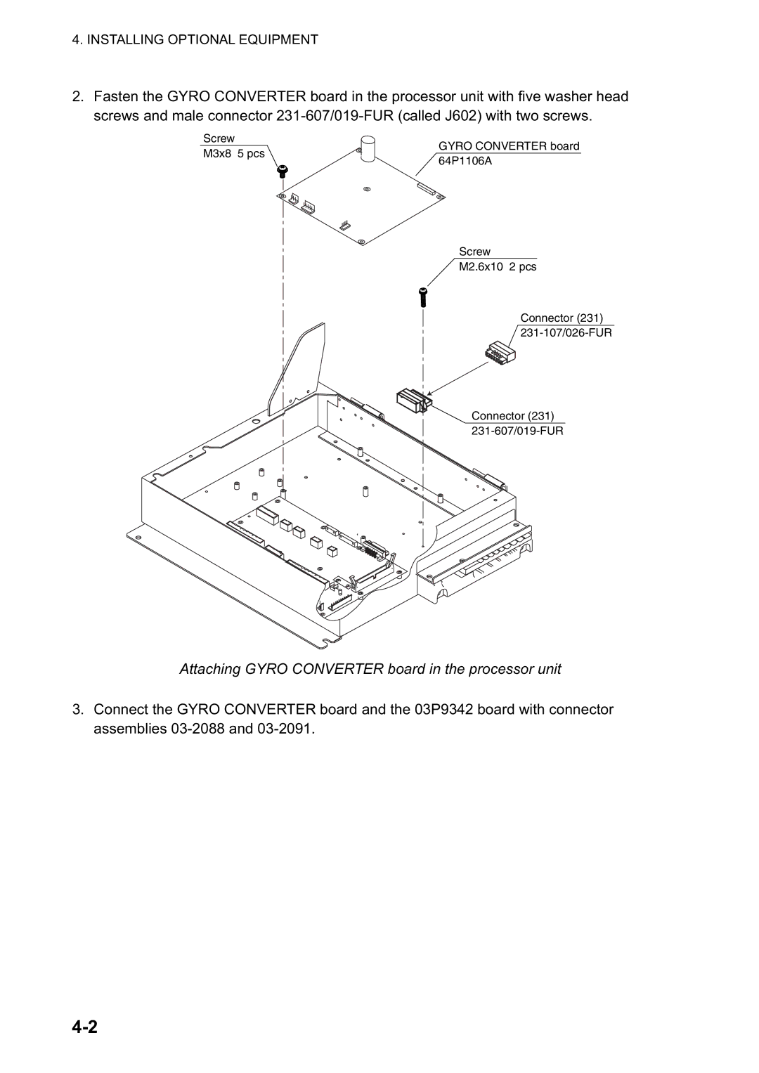
2.Fasten the GYRO CONVERTER board in the processor unit with five washer head screws and male connector
Screw M3x8 5 pcs
GYRO CONVERTER board 64P1106A
Screw
M2.6x10 2 pcs
Connector (231)
7
1
7
1
Connector (231)
Attaching GYRO CONVERTER board in the processor unit
3.Connect the GYRO CONVERTER board and the 03P9342 board with connector assemblies