GE Fanuc Automation
As Used in this Publication
Contents
Contents
GFK-1541B Contents
Introduction
Ethernet Communications System
Ethernet Interface
Capabilities of the Ethernet Interface
Port Descriptions
Ethernet Interface Ports
Ethernet Media
90-30 CPU374
PC Software Loader
Station Manager Software
GFK-1541B
Installation
CMM321 versions EF or earlier do not have a 10Base T port
Installing an IC693CMM321 Ethernet Interface Module
Restart Pushbutton
LEDs
Indication Function
GFK-1541B
Ports on the CMM321 RS-232, RJ-11 Port Station Manager Port
CMM321 Labels Default Station Address Label
Ethernet Ports
10Base-T Port
Equipment Required to Perform the Installation Procedures
Installing the CMM321 in the PLC
CMM321 Installation
CMM321 Configuration
Press Ethernet F2
CMM321 Configuration Parameters Ethernet Parameters
Station Manager PortParameters
Configuring Full-Duplex Operation
LED
Problems During Power-up
Approx Seconds
States of the Series 90-30 CMM321 Ethernet Interface
Waiting for IP
Determining If an IP Address Has Already Been Used
Pinging TCP/IP Ethernet Interfaces on the Network
CPU364
IC693CPU364 Series 90-30 CPU Module with Ethernet Interface
Ethernet Restart Pushbutton
GFK-1541B
10Base-T, RJ-45 Port
Ports on the CPU364 RS-232, RJ-11 Port Station Manager Port
Replaceable Surface Mount Fuse
CPU364 Labels Default Station Address Label
CPU364 Installation
Installing the CPU364 in the PLC
CPU364 Configuration
CPU364 Configuration Parameters Ethernet Parameters
GFK-1541B
Serial Port Parameters
Ethernet Interface Online
Verifying Proper Power-Up of the CPU364 Ethernet Interface
∗/
Software
Pinging TCP/IP Ethernet Interfaces on the Network
CPU374
IC693CPU374 Series 90-30 CPU Module with Ethernet Interface
Ports on the CPU374 RS-232, RJ-11 Port Station Manager Port
CPU374 Labels Default Station Address Label
CPU374 Installation
Installing the CPU374 in the PLC
CPU374 Configuration
CPU374 Configuration Parameters Ethernet Parameters
Serial Port Parameters
Advanced User Parameters
Verifying Proper Power-Up of the CPU374 Ethernet Interface
Pass?
EOK OFF
Pinging TCP/IP Ethernet Interfaces on the Network
IC697CMM742 Ethernet Interface
Installing the IC697CMM742 Ethernet Interface
Ethernet Restart Pushbutton
Ports on the CMM742
Service Option Connector
RS-485, D-Type Port Software Loader Port
Disable Onboard 10Base2 Port Jumper
CMM742 Labels Default Station Address Label
10BaseT Port
AUI Port
Installing the CMM742 in the PLC
CMM742 Installation
CMM742 Configuration
Press ethnet F2
CMM742 Configuration Parameters Ethernet Parameters
Serial Port Parameters
Verifying Proper Power-Up of the CMM742
approx.10-20 seconds
States of the Series 90-70 CMM742 TCP/IP Ethernet Interface
LED Pattern Where Stopped Possible Cause Corrective Actions
Pinging TCP/IP Ethernet Interfaces on the Network
Programming Srtp Channel Commands
Structure of the Communications Request
Communications Request
Elements of the Communications Request
Srtp Channel Commands
Commreq Command Block
Advantages of Channel Commands
Commreq Function Block
Status Data
Domain of a TCP connection Domain of a channel
Operation of the Communications Request
Comm REQ Sysid Task
Commreq Function Block and Command Block
Reserved
0AH
Type Value Description Decimal Hex
Establishing a Channel
Channel Commands
Aborting and Re-tasking a Channel
Retrieving Detailed Status on the Channel
Establish Read Channel
Example 1 Command Block-Basic Example
Value Meaning
Type Value Decimal Description
GFK-1541B Programming Channel Commands
GFK-1541B
Example 2 Command Block-Example using a Network Address Name
GFK-1541B
Establish Write Channel
Value Meaning
GFK-1541B Programming Channel Commands
GFK-1541B
Remote PLC Starting address at which to store data %R100
GFK-1541B
Send Information Report
Example1 Command Block-Basic Example
Value Meaning
GFK-1541B Programming Channel Commands
Word 24387 5F43 Remote Host Network Address name, char 3-4 C
GFK-1541B Programming Channel Commands
Abort Channel
Example Command Block
Retrieve Detailed Channel Status
GFK-1541B
Types of Status Data
Status Data
FT Output of the Commreq Function Block
Description of the Status Data
Status Bits Brief Description
LAN Interface Status LIS Bits
GFK-1541B
Each Srtp channel has a dedicated pair of bits as follows
Format of the Commreq Status Word CRS Word
Communications Status Words
Format of the Detailed Channel Status Words DCS Words
Error Status Major Error Description
Major Error Codes
Error Status Service Request Error Description
Minor Error Codes
Srtp Error Description
Minor Error Codes for Major Error Codes 5H and 85H
Error codes specific to Series 90-30 CPU374
Error Status Application Interface Error Description
Minor Error Codes for Major Error Code 90H at Client PLC
Response to session request did not arrive in proper order
Essential Elements of the Ladder Program
Controlling Communications in the Ladder Program
Commreq Example
GFK-1541B
Troubleshooting Your Ladder Program
Commreq Status Word is Not One
Commreq Status Word is Zero 0 and FT Output is OFF
Monitoring the Communications Channel
Backplane Communications with PLC Fault Lost Request
Monitoring the Channel Error Bit
Monitoring the Data Transfer Bit
How To Re-Task a Channel
Use Channel Re-Tasking To Avoid Using Up TCP Connections
Managing Channels and TCP Connections
Programming Modbus/TCP Channel Commands
Communications Request
Modbus/TCP Channel Commands
Domain of a TCP connection Domain of a channel
Cimplicity ME
Commreq Command Block
Type Value Description Decimal Hex
Open a Modbus/TCP Client Connection
Modbus TCP Channel Commands
Dec Hex
Command 3000 Example
Close a Modbus/TCP Client Connection
Command 3001 Example
Read Data from a Modbus/TCP Device
Command 3003 Example
Value Type Decimal Description
Command 3003, Example
Command 3003, Example 3 Read Exception Status
Write Data to a Modbus/TCP Device
Command 3004, Example 1 Set Single Register
Command 3004, Example 2 Force Single Coil
Command 3004, Example 3 Set Multiple Registers
Status Data
LAN OK
Status Bits Brief Description
Each Modbus channel has a dedicated status bit
8BH
Minor Error Codes for Major Error Codes 90H Client API Error
Busy
Error Description
Controlling Communications in the Ladder Program
Commreq Example
GFK-1541B
GFK-1541B Programming Modbus/TCP Channel Commands
GFK-1541B
GFK-1541B Programming Modbus/TCP Channel Commands
GFK-1541B
Commreq Status Word is Zero 0 and FT Output is OFF
Troubleshooting a Ladder Program
Monitoring the Channel Open Bit
Sequencing Communications Requests
Ethernet Global Data
Overview of EGD
Configuring the Exchange
Exchange
Producer
Configuring the Producer ID
Consumer
PLC Producing EGD Via LAN PLC Consuming EGD
Asynchronous Operation of EGD
Effect of PLC Modes and Actions on EGD Operations
PLC Mode or Action
Maximum Number of Exchanges
Exchange Limitations and Recommendations
Maximum Data Size of an Exchange
Number of Variables
Allowable Data Types in Exchanges
Update Timeout Period
Producer and Consumer Period Ranges
Effect of Enabling User Interrupts
Timing Considerations for the Series 90-30 CPU374
General PLC Timing Considerations when using EGD
Naming Conventions Example
Naming Conventions
Record Your EGD System Information
Before You Configure EGD Exchanges
Record Your Produced Exchange Information
Recording Exchange Information
Exchange Definitions
Configuring EGD
Produced Data Exchange Definition
Status Word
Reply Rate
Group ID
Consumed Data Exchange Definition
Time Stamp
Configuring Ethernet Global Data
Produced Exchange Information Example
=Producer =Consumer Use your own IP addresses here
Variable List for Consumed Exchanges Example
Variable List for Produced Exchanges Example
Type Value Description Producer Decimal Consumer
Valid PLC Memory Types Used with EGD
Setting Aliases for Remote Network Adapters
Configuring the Ethernet Interface Adapter Name
Adapter Names, Aliases, and Groups
Group ID IP Address
Group Usage
Exchange Status Word
Sntp error
Exchange Status Word Error Codes
Simple Network Time Protocol Sntp
Configuring an Ethernet Interface for Sntp
Timestamping EGD Exchanges
Normal Sntp Operation
Multiple Sntp Servers
Loss or Absence of Sntp Timing Signals
Network Administration Support
IP Address Format for Network Classes A, B, C
IP Addressing
Range of first integer Class
Multicast IP Addresses
IP Addresses Reserved for Private Networks
Networks Connected by a Gateway
Gateways
Subnet Addressing and Subnet Masks
Subnets and Multiple Gateways
Gateway
Example Network Divided into Two Subnets
Example Configuring Multiple Gateways
Configuring Multiple Gateways
IP Address Subnet Mask Default Gateway IP Address
Module Configuration for the Ethernet Interface in PLC B
Network Address Naming Architecture
Default DDP Network Address Name
Name Assignment
DDP Name Assignment
Local Name Table Name Assignment
Name Resolution
Name Usage
DDP Name Resolution
MAC Addresses
Troubleshooting
Diagnostic Tools Available for Troubleshooting
What to do if you Cannot Solve the Problem
PLC Fault Table
PLC Fault User Action
PLC Fault Table Descriptions
PLC Fault Table Descriptions
AUP See Advance User Parameters
Advanced User Parameters AUP
GFK-1541B
Extended Netid See Subnet Id
Bootp
GFK-1541B
GFK-1541B Appendix a Glossary
GFK-1541B
GFK-1541B Appendix a Glossary
GFK-1541B
IC697CMM742 Series 90-70 Ethernet Interface Type 2, Ports
Communications Port Characteristics
RS-232, RJ-11 Serial Port
Port Settings
Port Pinout
Station Manager Serial Port Pinout
Station Manager Serial Cable IC693CBL316A
Serial Cable IC693CBL316A Connector Pinouts
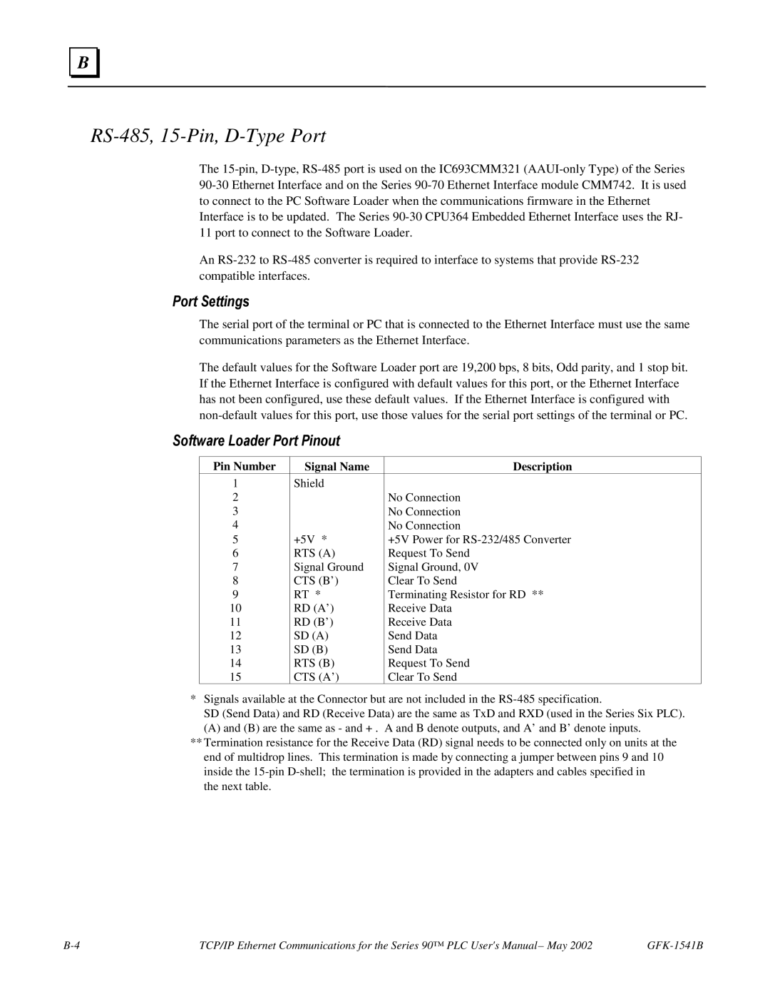
RS-485, 15-Pin, D-Type Port
Pin Number Signal Name Description
Software Loader Port Pinout
Part Numbers for GE Fanuc Cables and Converters
Cable Assembly IC690ACC901
Part Number Description
10Base-T Port
Pin Number Signal Description
10Base T Port Pinouts
Connection to a 10Base T Network
10Base-T/100Base Tx Port
10Base-T/100Base Tx Port Pinouts
Direct Connection to the CPU374 Ethernet Interface
Connection to a 10Base-T / 100Base Tx Network
10Base2 Port Pinouts
10Base2 Port
Other Network Devices 10Base2 Cable
Ethernet Aaui Port Pinouts
Aaui Port
GE Fanuc Transceivers
Aaui Transceiver Information
GE Fanuc Catalog Network Connection Comments Number
LED Indicator Lights
Power Requirement
IC649AEA102 Ethernet 10Base-T Transceiver
IC649AEA102 Transceiver Connection
IC649AEA103 Ethernet 10Base2 Transceiver
LED Indicator Light
IC649AEA103 Transceiver Connection
Pinouts of the AUI Port
AUI Port
10Base2 Transceiver Description
AUI Transceiver Cable Connection
PC Software Loader
Updating Firmware Under Windows
To install the new firmware, perform the following steps
Restarting an Interrupted Firmware Upgrade
Updating Firmware Under DOS and Windows
Sending Attach try #
Boot Mode Active
Ethernet Interface Installation and Configuration
Using the IC697CMM742 with PLC CPU Versions 4.12
GFK-1541B
TCP/IP
Chsosw ipaddress a.b.c.d
= None
Startup
Ethernet Interface Operational Restrictions
Station Manager
Software Loader
Bits Bit words AI1 257 16641 AQ1 16897 29185 61825
GFK-1541B
Index
Index
Ports, Ethernet
Powering-up
SQE