3.Counting ceases upon receipt of the trailing edge of a sync signal. The SV Series determines that at least the number of bar codes expected (programmed) during the sync period have been fully decoded. If not, an internal No Read condition is set for possible reporting through communication or output activation.
4.The SV unit then waits for the next leading edge of a sync signal to begin counting codes being scanned and analyzed.
Note: For best performance in either sync mode, mount the SV unit in a location where a bar code is not in the laser beam when an active edge signal is received.
Communication Sync Commands
Sync operation can be accomplished through serial communications. Please see the ~SK# (page
Output Ports
Five programmable output ports are available on I/O connector pins 5, 6, 7, 8, and 15. Each port can be programmed to activate on practically any combination of data and analysis parameters (including “good codes”) analyzed by the SV Series. Port activation logic and parameters are programmed via the output interface modes and associated commands. See the "Output Interface Modes Descriptions" on page
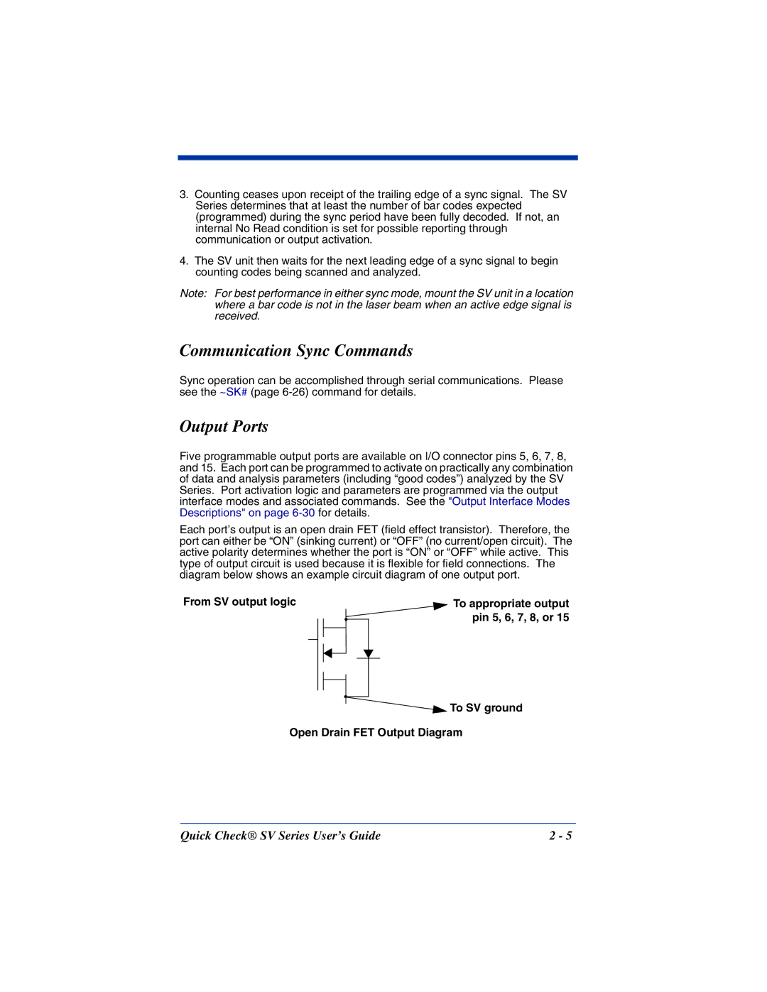
Each port’s output is an open drain FET (field effect transistor). Therefore, the port can either be “ON” (sinking current) or “OFF” (no current/open circuit). The active polarity determines whether the port is “ON” or “OFF” while active. This type of output circuit is used because it is flexible for field connections. The diagram below shows an example circuit diagram of one output port.
From SV output logic |
|
|
| To appropriate output | |||||
|
|
|
|
|
|
|
|
| pin 5, 6, 7, 8, or 15 |
|
|
|
|
|
|
|
|
| |
|
|
|
|
|
|
|
|
|
|
|
|
|
|
|
|
|
|
|
|
|
|
|
|
|
|
|
|
|
|
|
|
|
|
|
|
|
|
|
|
|
|
|
|
|
|
|
|
|
|
|
|
|
|
|
|
|
|
|
|
|
|
|
|
|
|
|
|
|
|
![]()
![]() To SV ground
To SV ground
Open Drain FET Output Diagram
Quick Check® SV Series User’s Guide | 2 - 5 |
