Application Manual
Page
Limited Warranty and Imitation of Liability
Page
Safety Precautions
Required
Prohibited
Page
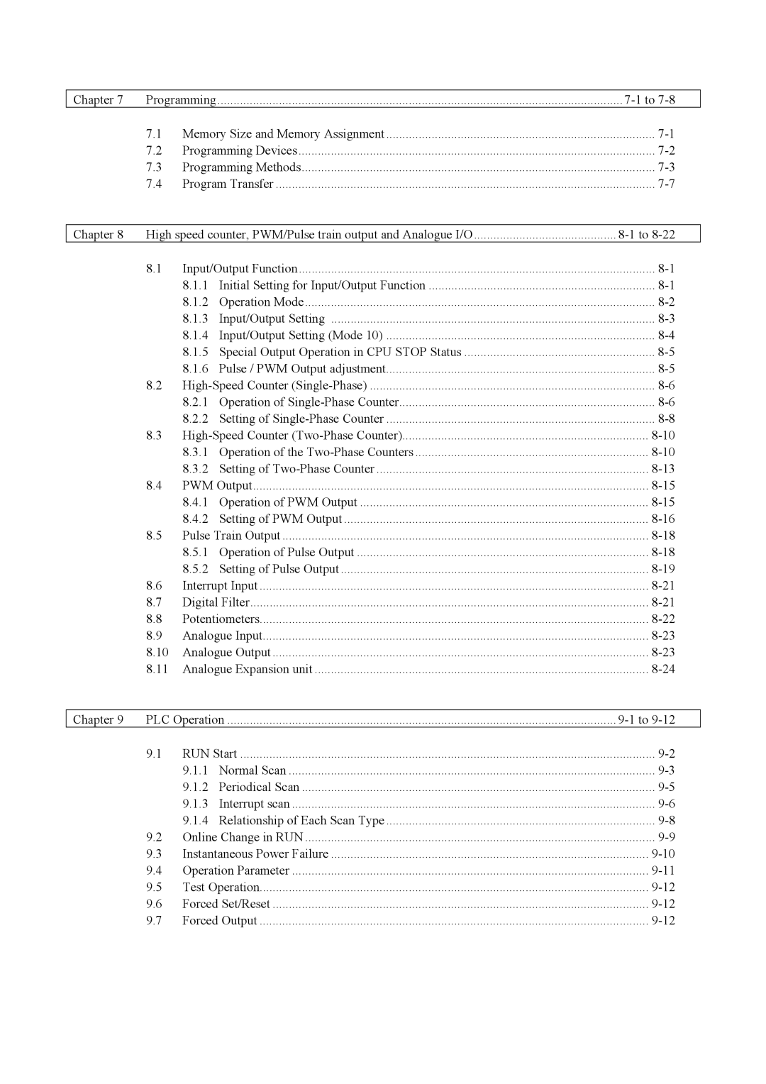
Table of Contents
High-Speed Counter Two-Phase Counter
Input/Output Setting
High-Speed Counter Single-Phase
Memory Size and Memory Assignment
Operation Error Codes
Connecting to the Ports
Syntax and Assembler Error Codes
Error Display and Actions
Memo
Maintaining programs without a battery
Remote maintenance through modem connection
Easily adjustable potentiometer
Compliant with overseas specifications as standard
Memo
System Overview
23,28-point type system configuration diagram
Device name Description
Chapter Function and Performance Specifications
General Specifications
Device that has been connected
Function Specifications
Timer counter is provided internally
WR, DR
Off to stop operation
Is running, operation stops and the outputs are aborted OFF
General purpose port
R7EC
Interrupt input
Performance Specifications
Calculation Specifications
Specification
Input Specifications
Circuit diagram
OFF → on
Output Specifications
Y100 of EH-*23DRP/A23DRT/*28DRP/*28DRT
Output specification
Ms max 24 V DC 0.2A
Number of output points See Chapter Number of common
Load current Common Output
Ms max 24 V DC 0.2A Response time
Maximum Circuit Load current Common Output
Maximum Circuit A 240 V AC Load current Common
Externally supplied power
Ms max
At 1 cycle or less/common
Analogue Input Specifications
High-Speed Counter Specifications
PWM Output/Pulse Train Output Specifications
Point and 28-point type 10/14/28-point Relay Output
Circuit diagram Analog expansion unit
Analogue Output Specifications
Circuit diagram 23 points type
Module type Points type module Analog exp. unit
Backup
Potentiometer Analogue Input Specifications
Interrupt Input Specifications
Expansion
Clock Function
Power Supply for Sensor
Product lineup
Others Model
Name and function of each part Type
10-Point Basic Unit
Detailed explanation Remarks
14-Point Basic Unit
EH-*14
EH-*23 EH-*28
23-Point and 28-Point Basic Unit
To the right
Expansion Unit
Name and function of each part
Power supply 24V DC Load power supply 24V DC 100-240V AC
Terminal Layout and Wiring
RUN
AC power supply
AC power supply 100-240V AC Load power supply 24V DC
DC power supply 24V DC
Input
Power supply 24V DC 12/24V DC
Power supply 24V DC Output Load power supply 12/24V DC
Power supply 24V DC
Output Load power supply 12/24V DC
WRF06E
Output Power supply 24V DC
Output Power supply 100-240V AC
Power supply 24V DC Output
100-240V AC Input Output
Output Power supply
24V DC 12/24V DC
Input Output Power supply 100-240V AC
Load power supply 24V DC, 100-240V AC Output
IO6 OC7 VO7
EH-D6EAN Example of current input and current output
Current input ⋅
OC6 VO6 IO7
Type Weight
Weights and Power Consumption
100V AC 264V AC 24V DC Normal Rush
Exterior Dimensions
140 150
Memo
List of Instructions
Instruction Classifications
Instruction classification table Description Type
TD, SS, CU CTU, CTD, CL
TD, SS, CU, CT
Nand
RES
Basic instructions timer, counter
WX, WY, WR
Basic instructions relational box
DX, DY, DR
Item number Ladder symbol Instruction symbol
DR, DM
BCD
WR, WM
Number
Instruction symbol Process descriptions
Instruction symbol Process descriptions Name
WY, WR, WM
BCD →
Processing time when n=1
WM, TC
FUN instructions
PWM
BOX
Instruction Specification Details
Remark
Item number
Ladder format Condition code
Bit Word Double word Constant Usable I/O
Contact serial connection AND, ANI
Basic instructions-3
ANI
Condition
Basic instructions-5
Contact parallel connection OR, ORI
ORI
Instruction format
Basic instructions-7
Negation not
Not
DIF n
Basic instructions-8
Leading edge detection and DIF, or DIF
Number To 511 Decimal
Trailing edge detection and DFN, or DFN
Basic instructions-9
DFN n
Bit Word Double word
Usable I/O Other
Word Double word Constant Other
Usable I/O Bit
WX WY WM DX DY TD, SS
Remark
Set start/reset cancel master control MCS, MCR
Basic instructions-13
Upper case MCS
MRD
Ladder format
MPS
MPP
Logical block serial connection ANB
Basic instructions-18
See Function column
Basic instructions-19
Logical block parallel connection ORB
Bit Word
Basic instructions-20
Processing box start and end Processing BOX
Indicates the start and end of the processing box
Relational box start and end Relational BOX
Basic instructions-21
Function Indicates the start and end of the relational box
Basic instructions-22
On delay timer on Delay Timer
OUT TD n t s
Time chart
OUT SS n t s
Basic instructions-23
Single shot Single Shot
TMR, CU
Conditions are ignored because it uses edge trigger
SS11 turns off when set value ≥ progress value
Progress value is updated
SS11 is turned on at the leading edge of X00001 again,
OUT CU n s
Basic instructions-24
Counter Counter
Counter number To 255 Decimal Set value To 65535 Decimal
Ignored X00005 CL15 CU15 Set value Progress Value CU15 TC15
UP/DOWN Counter
CTU17
OUT CL n s
Basic instructions-27
Counter clear Counter Clear
Counter number To 255 Decimal
Word Double word
Condition Steps
Command format
Double word LD, and s1S==s2 Or s1S==s2
Relational box Relational BOX
When WR0000 ≠ WR0002, R003 turns on
Basic instructions-30
26.8 Lower case DW
BOX
Double word LD, and s1Ss2 Or s1Ss2
Word See Notes 37.5 Double word
When WR0000 WR0002, R005 turns on
Basic instructions-32
S1 s2 Steps
SignedRelational box Signed Relational BOX
When DR0000 DR0002, R006 turns on signed
Basic instructions-33
Off
≤ Relational box ≤ Relational BOX
When WR0000 ≤ WR0002, R007 turns on
Basic instructions-34
S1 = s2
Double word LD, and s1S=s2 Or s1S=s2
= s
Arithmetic instructions-1
Substitution statement Assignment Statement
See following table
Substituted into WR0000 at the leading edge of input
X00001
Designated by WR0000 + WM000
Word Double word
Arithmetic instructions-2
Binary addition Binary Addition
Substitution destination Augend Addend
115 Lower case DW
Arithmetic instructions-3
Word 177 Double word
Substitution destination Minuend Subtrahend
Arithmetic instructions-4
Binary subtraction Binary Subtraction
Positive Negative
104 Lower case DW
Arithmetic instructions-5
BCD subtraction BCD Subtraction
Word 163 Double word
Word 112 Double word
Arithmetic instructions-6
Binary multiplication Binary Multiplication
Substitution destination Multiplicand Multiplier
164 Lower case DW
Arithmetic instructions-7
BCD multiplication BCD Multiplication
Word 447 Double word
143
Signed binary multiplication Signed Binary
Multiplication
= s1 / s2
Arithmetic instructions-9
Binary division Binary Division
= s1 / s2 Word 110 Double word
= s1 B/ s2
Arithmetic instructions-10
BCD division
152 Lower case DW
= s1 S/ s2
Arithmetic instructions-11
Signed binary division
101
= s1 or s2
Arithmetic instructions-12
Logical or
Upper case B
= s1 and s2
Arithmetic instructions-13
Logical
= s1 and s2 Bit, word Double word
= s1 XOR s2
Arithmetic instructions-14
Exclusive or
= s1 XOR s2 Bit, word Double word
= s1 == s2
Arithmetic instructions-15
= Relational expression
= s1 == s2 Is a word Is a double word
108
Signed = Relational expression
= s1 S== s2
= s1 S== s2 Is a double word
= s1 s2
Arithmetic instructions-17
= s1 s2 Is a word Is a double Word Bit Double word
= s1 S s2
Signed Relational expression
= s1 S s2 Is a double word
Arithmetic instructions-19
= s1 s2 Is a word Is a double word
Arithmetic instructions-20
= s1 = s2
Arithmetic instructions-21
≤ Relational expression
= s1 = s2 Is a word Is a double word
= s1 S= s2
Signed ≤ Relational expression
= s1 S= s2 Is a double word
Bset d, n
Application instructions-1
Bit set
Bit location to be set Constant is set Decimal
Application instructions-2
Bit reset
Bres d, n
Bit test
Application instructions-3
BTS d, n
Also, the 20th bit of DR0102 is reset to 0 by Bres
Also, the 20th bit of DR0104 is checked by BTS
SHR d, n
Application instructions-4
Shift right
After execution
DIF1
Shift left
Application instructions-5
SHL d, n
Rotate right
Application instructions-6
ROR d, n
Rotate left
Application instructions-7
ROL d, n
B31 DR0002
Logical shift right
Application instructions-8
LSR d, n
LSL d, n
Application instructions-9
Logical shift left
If d is a word
BCD shift right
Application instructions-10
BSR d, n
BCD shift left
Application instructions-11
BSL d, n
Below
Application instructions-12
Block transfer Move
If n is a word
Words of data are transferred
Copy d, s, n
Application instructions-13
Copy
Below Copy d, s, n
Default value H2020 is set in the range of WR0100 to WR01FE
R7F4 R7F3 R7F2 R7F1
Application instructions-14
Block exchange Exchange
XCG d1, d2, n
Application instructions-15
Reverses the contents of d
To be reversed
NEG d
Application instructions-16
Twos complement Negate
To take complement
ABS d, s
Application instructions-17
Absolute value
ABS d, s Word Double word
Before conversion
Application instructions-18
Binary → BCD conversion
BIN
After conversion BIN Before conversion
Application instructions-19
BCD → Binary conversion
BCD
Average
Application instructions-20
Decode
105 115 195 317 481 829 1586
Encode
Application instructions-21
128 187 126
Bit count
Application instructions-22
Number of bits set to That counts the bits Set to
Swap d
Application instructions-23
Swap
Swaps the upper 8 bits and lower 8 bits contained in d
Unit
When n=0, it is not executed When n5, it is not executed
Application instructions-24
Unity result write Destination I/O
Input Point type Output
Application instructions-25
When n=0, it is not executed
Distribute
X01001 DIF0 Dist WR0000, WX0000 LD X00001 and DIF0
714
Control instructions-1
Normal scan end
Instruction for use
101
Special internal output Error code Error description
102
CU, CT
Control instructions-4
Conditional jump
Code number To 255 Decimal Jump condition
Nesting of JMP instructions is allowed
Syntax of JMP, Cjmp
104
LBL n
Control instructions-5
Label
WRF001 H0001 Duplicate definition of LBL
For the instruction instruction, see Next n
Control instructions-6
Code number To 49 Decimal
106
Next
Control instructions-7
107
Syntax of for to Next
108
109
SB n
Control instructions-9
Start subroutine program
WRF001 H0004 Duplicate definition of SB H0013 SB undefined
RTS
RTS DER ERR
111
To 2 , 16 to 19
Control instructions-11
Start interrupt scan program Interrupt
To 27 Decimal
End interrupt scan program Return Interrupt
Control instructions-12
113
Nesting of subroutines is allowed up to 5 levels
Syntax of SB n, RTS, INT n and RTI
114
Usable I/O Others
Baud rate Value
+A Data length Byte +B H80 †† ††=Start code
+C H0000
118
WR0
Sample program
R7E3
DIF0
TRNS/RECV command return code table
Name Description Countermeasure
Recv 0 d, s, t
Transfer command-2
064
122
123
Argument
General purpose port switching
FUN instructions-1
124
432
FUN instructions-2
Refresh All points
Argument dummy
244
FUN instructions-3
Refresh Input/output
Input type
127
128
147
FUN instructions-5
High-speed Counter Operation Control
Argument Counter Number, operation Control value
138
FUN instructions-6
High-speed Counter Coincidence Output Control
Argument Counter Number, output Instruction
131
FUN instructions-8
High-speed Counter Current Value Replacement
Argument counter Number Replacement value Storage area
Rewrite the count value of the counter No to
132
FUN instructions-9
High-speed counter current value reading
Argument counter Number Current value storage Area
134
162
High-speed counter preset
FUN instructions-11
135
136
137
173
FUN instructions-13
138
139
149
FUN instructions-14
Pulse output control
Argument Pulse output Number
217
Pulse frequency output setting changes
FUN instructions-15
141
142
919
FUN instructions-16
Pulse output with acceleration/deceleration
143
144
145
146
Usable I/O classifications and point types
I/O Assignment
Type Assignment Point
Shows a diagram outlining this series of operations
External I/O Numbers
List of I/O number conventions for external I/O
List of external I/O classification and data type
Classification Data type Remarks
Data type Numbering convention Example
DR0
Internal Output Numbers
WR0
WM0
Sram
Lists the programming specifications for the MICRO-EH
Memory Size and Memory Assignment
Flash
Programming Devices
Following methods are used to create the user programs
Ladder Editor
System configuration using a personal computer
Programming Methods
WVCB02H WPCB02H
Modify Test operation, adjustment
Out-line of opera-ting procedure Situation Point
List of procedures for creating a program
On-line On-direct
Size of one circuit
Example when using loop symbols
Example when using a processing box
Program Transfer
WRF03D
WRF01A
WRF03C
WRF06B
Change individual setting Store the settings in the memory
Initial Setting for Special Input/Output Function
Input/Output Function
Operation Mode
Operation mode list
Input/Output Setting
Special internal output for setting detailed function
„ Outline
Y100 Group „ Mode setting Y101 Y102 Group 2 Group
„ In/output setting
„ Example
R7FC toR7FF
Pulse / PWM Output adjustment
Special Output Operation in CPU Stop Status
Counter output
Operation of Single-Phase Counter
High-Speed Counter Single-Phase
Basic operation
Preload input operation
Current value clear instruction operation
Setting of Single-Phase Counter
WRF058 Counter
At abnormal setting
Individual counter setting
WRF059 Counter
Operation of Two-Phase Counters
High-Speed Counter Two-Phase Counter
Phase counting mode
High ↓ Falling edge
↓ Falling edge Low ↑ Rising edge High
High ↓ Falling edge Low
↓ Falling edge High
↑ Rising edge Low
↑ Rising edge High
WRF072
Setting of Two-Phase Counter
Diagnostic error
WRF076
WRF058 Two-phase counter
Bit Description
PWM Output
Operation of PWM Output
Setting the PWM output frequency
Setting the PWM Output
Setting the PWM output on-duty value
WRF058 PWM output
Setting abnormality
Individual PWM output setting
WRF059 PWM output WRF05A PWM output
Pulse Train Output
Operation of Pulse Output
Setting the number of output pulses
Setting of Pulse Output
Setting the pulse output frequency
Number of output pulses for pulse output
WRF058 Pulse output
Individual setting of pulse outputs
WRF059 Pulse output
Interrupt input correspondence table Terminal INT No
Interrupt Input
Digital Filter
Input sampling number
Potentiometers
Analogue Input
Analogue Output
Sw1 Sw2 Range Remarks
Sw6 Conversion mode Remarks
Analogue Expansion unit
Sw3 Sw4 Range Remarks
RUN mode when the RUN input is On
Switch Stop or
Specification. a 10-point type CPU becomes
Input on
RUN Start
Program classification Description Expression
Normal Scan
Definition and operation
Scan time Congestion check time
Causes of congestion errors at normal scan
RTI RTI INT0INT0
10 Congestion error at periodical scan 10 ms
Periodical Scan
Interrupt Scan
Continuation of operation after a congestion error
Stop
Scan Program execution Interrupt contact on
Interrupt contact on Congestion check time
INT16 INT17 INT18 INT27
Relationship of Each Scan Type
List of interrupt label Interrupt label Cause of startup
Conditions for performing program change while running
Online Change in RUN
CPU Halt time
Instantaneous power failure actions
Instantaneous Power Failure
Powering on
RUN OFF
Function Description When to use the function
Operation Parameter
Test Operation
Forced Set/Reset
Forced Output
Installing the unit
Installation
Installation location and environment
Mounting to a DIN rail
10-2
Separation of the power system
Wiring
10-3
Unit Screw Clamping
Wiring to the power module
10-4
Wiring to the input terminals DC input AC input
10-5
EH-*XXDT
Wiring to the output terminals Relay output
Transistor output
Transistor output Source type
Life characteristics 125 V AC
10-7
Wiring to the unit terminals
10-8
Port
Communication port specification
Port function
Ascii
Remarks
Off H8000 Transmission procedure 4800 bps
11-2
Bit WRF03D Initial value
Port 2 specifications
Setting port
11-3
Port 2 hardware
General purpose port Port 1,2
1n station communication on RS-485
11-4
AT Commands
Configuration
Modem Control Function
Register Set value Function
List of commands extract
Command Function overview Example
Number format Word format
Sequence
11-7
Connecting to the Ports
Port
Case of RS-422
Connection for 1n station communication by RS-485 11-9
11-10
Error Codes
R7CF
Error Error name Classifi
Code Detection timing Cation
Failure detection
For
Syntax and Assembler Error Codes
LBL
INT
JMP
Operation Error Codes
CAL
Cjmp
R7CB
Name Meaning Description Setting Resetting Condition
Bit Special Internal Output Area
R7CE
12-6
12-7
WRF07B
List of special internal outputs that can be stored
Special internal output Function That can be stored
WRF07C WRF07D WRF07E
Name Storage data
Setting Resetting Condition
12.5
12-9
Name Storage data Description Setting
12-10
Name Stored data Description
PI/O function Individual setting Request
12-11
Name Stored data Description Setting Resetting
12-12
13-1
Error Display and Actions
Ladder Editor
13-2
Error code Error name Corrective action
Process flow when an error occurred is shown below
13-3
13-4
Checklist when Abnormality Occurred
13-5
CPU LED, I/O LED
Procedures to Solve Abnormality
13-6
Power supply check
13-7
13-8
13-9
13-10
Data cannot be entered
Assignment error is generated, but data is read
13-11
13-12
13-13
Assignment error occurred, but output is normal
CPU operates, but output signals are not detected
13-14
13-15
13-16
Detailed operation example
Operation verification procedures
Peripheral unit name Form
14-1
E P 1 Starting the Ladder Editor for Windows
14-2
Menu bar
Select H-302 for the CPU type setting
E P 2 Initialization
14-3
Assign in the Menu bar
14-4
Setting from the I/O Assign List
14-5
Setting from the Slot Setting Status
14-6
Click the OK button. The dialogue closes
E P 3 Program Input
14-7
Click the OK button in the Processing Box
14-8
M, Y, TD, SS, WDT, MS, TMR, CU, RCU, CTU, CTD, CL
Input I/O No., time base, and the first setting value
14-9
Click the circuit write icon Tool bar
Input comparison expression and comment Click the OK button
14-10
E P 4 Checking Program Errors
14-11
E P 5 Saving the Program
14-12
E P 6 Program Transfer to CPU
14-13
Click File → CPU write in the Menu bar
14-14
I/O Monitor dialogue box is displayed
E P 7 Monitoring Verifying the Operation
14-15
Monitor and display 16 points from Y100
Click the icon in the Symbol bar
I/O monitor can be specified in the following two ways
14-16
Daily inspection
Normal status Main cause of error
Life of the power module
Items for daily inspection
How to replace the battery
Life of the battery
15-2
ORI
LDI
ANI
Not
EH-150 200 250 252 2000 2002 4010 700 1002 300 702 302
Arithmetic instructions Instruction Instruction name
Application instructions 2/2 Instruction Instruction name
Free
FUN instructions 1/5 Instruction Instruction name
FUN instructions 2/5 Instruction Instruction name
FUN instructions 3/5 Instruction Instruction name
FUN instructions 4/5 Instruction Instruction name
FUN instructions 5/5 Instruction Instruction name
Appendix 2 Standards
Standards