HP EliteBook 9470m Notebook PC
Maintenance and Service Guide
Copyright 2012, 2013 Hewlett-Packard Development Company, L.P
Safety warning notice
iv Safety warning notice
External component identification
Table of contents
Removal and replacement procedures
Product description
5 Computer Setup BIOS and Advanced System Diagnostics
7 Backup and recovery
6 Specifications
Index
Power cord set requirements
Statement of Volatility
Recycling
Product Name
1 Product description
Category
Description
Flash cache
Category
Description
Memory
Ethernet
Wireless
Category
Description
Ports
Power requirements
Category
Description
Operating system
Preinstalled
Category
Description
Description
Preinstalled with Microsoft Office
Chapter 1 Product description
Category
Category
Restore media-DR-DVD
Restore media-OS-DVD
Serviceability
Description
2 External component identification
Display
Component
Programs HP HP Webcam
TouchPad
Component
Description
Chapter 2 External component identification
Component
Description
Lights
Component
Description
Buttons and fingerprint reader select models only
NOTE Windows 8 keyboard shown
Chapter 2 External component identification
Select Start Control Panel System and
Security Power Options
Component
Description
esc key
Keys - Windows models
Component
Description
fn key
Keys - SUSE Linux models
Component
Description
Description
Front
available power source has reached a low battery
Component
Description
Left
Regulatory, Safety, and Environmental Notices . To access
Component
Description
Right
Chapter 2 External component identification
Component
Support
Bottom
Component
Description
Contains the battery. Supports a wireless subscriber
Battery release latch
Releases the battery from the battery bay
Battery bay and SIM slot
Service tag and PCID label
Service tag
3 Illustrated parts catalog
Windows 8 models Non-Windows 8 models
PCID label
Computer major components
Spare part number
Touchpad assembly not illustrated
AC power connector
Component
Spare part number
RTC battery
Service cover
Component
702870-001
19 Solid-state drive includes bracket, connector, and screws
Component
Spare part number
Display assembly subcomponents
For use on models with a webcam
Component
Spare part number
Display bezel
Spare part number
Mass storage devices
Description
AC adapter
Miscellaneous parts
Component
Spare part number
number
Sequential part number listing
Spare part
Description
number
Chapter 3 Illustrated parts catalog
Spare part
Description
flag
Spare part
Description
number
number
Chapter 3 Illustrated parts catalog
Spare part
Description
number
Sequential part number listing
Spare part
Description
Cables and connectors
4 Removal and replacement procedures
Preliminary replacement requirements
Service considerations
Grounding guidelines
Drive handling
Electrostatic discharge damage
Typical electrostatic voltage levels
Relative humidity
Event
Workstation guidelines
Packaging and transporting guidelines
Equipment guidelines
Material
Voltage protection level
Battery
Component replacement procedures
Page
Display assembly components panel, bezel, webcam, microphone
Chapter 4 Removal and replacement procedures
4. If it is necessary to replace the webcam/microphone module
b. Disconnect the cable 2 from the webcam/microphone module
708771-001 - 35.6-cm 14.0-in, LED, HD+, AntiGlare display panel
Component replacement procedures
5. If it is necessary to replace the display panel
702871-001 - 35.6-cm 14.0-in, LED, HD, AntiGlare display panel
Chapter 4 Removal and replacement procedures
Hard drive cover
Hard drive/SSD drive
a. Remove the connector from the hard drive
Reverse this procedure to reassemble and install the hard drive
Component replacement procedures
mSATA drive
Reverse this procedure to install the mSATA drive
Component replacement procedures
2. Remove the drive 2 by pulling it away from the slot at an angle
RTC battery
Service cover
2. Click Support & Drivers Drivers & Software
Update BIOS before adding memory modules
6. Under Step 2 Select a Download, click the BIOS link
Memory module
Reverse this procedure to install a memory module
Component replacement procedures
Remove the memory module
WWAN module
Component replacement procedures
Reverse this procedure to install the WWAN module
WLAN module
Component replacement procedures
Reverse this procedure to install the WLAN module
Keyboard
Release the small keyboard connector 5 and remove the cable
7. Release and disconnect the following connectors and cables
Release the pointing stick connector 1 and remove the cable
Release the large keyboard connector 3 and remove the cable
Chapter 4 Removal and replacement procedures
8. Remove the keyboard Reverse this procedure to install the keyboard
b. Hard drive see Hard drive/SSD drive on page
c. Service cover see Service cover on page
Base enclosure
a. Hard drive cover see Hard drive cover on page
Chapter 4 Removal and replacement procedures
a. Hard drive cover see Hard drive cover on page
Touchpad
e. Base enclosure see Base enclosure on page
c. Service cover see Service cover on page
b. Hard drive see Hard drive/SSD drive on page
Power connector
c. Service cover see Service cover on page
a. Hard drive cover see Hard drive cover on page
Reverse this procedure to install the power connector
2. Disconnect the power connector cable from the system board
3. Lift the power connector from the computer
4. Remove the power connector
d. Keyboard see Keyboard on page
c. Service cover see Service cover on page
a. Hard drive cover see Hard drive cover on page
b. Hard drive see Hard drive/SSD drive on page
System board
c. Service cover see Service cover on page
a. Hard drive cover see Hard drive cover on page
WWAN module see WWAN module on page
d. Fan see Fan on page e. Keyboard see Keyboard on page
f. Base enclosure see Base enclosure on page
Memory module see Memory module on page
Reverse this procedure to install the system board
Component replacement procedures
3. Lift the left side of the system board up at an angle
g. Keyboard see Keyboard on page
Heat sink
d. WLAN module see WLAN module on page
e. WWAN module see WWAN module on page f. Fan see Fan on page
Reverse this procedure to install the heat sink
Component replacement procedures
2. Remove the heat sink
c. Service cover see Service cover on page
Speaker assembly
e. Base enclosure see Base enclosure on page f. Fan see Fan on page
g. System board see System board on page
b. Hard drive see Hard drive/SSD drive on page
Smart card board
c. Service cover see Service cover on page
a. Hard drive cover see Hard drive cover on page
Reverse the removal procedures to install the smart card board
Chapter 4 Removal and replacement procedures
Remove the smart card board
b. Hard drive see Hard drive/SSD drive on page
Fingerprint reader board
c. Service cover see Service cover on page
a. Hard drive cover see Hard drive cover on page
b. Hard drive see Hard drive/SSD drive on page
Display assembly
c. Service cover see Service cover on page
a. Hard drive cover see Hard drive cover on page
2. Release the display panel cable from the routing channel
NOTE Be sure to support the display when removing the screws
5. Remove the display assembly from the top cover
Component replacement procedures
7. To remove the display panel
Display panels are available using the following spare part numbers
Chapter 4 Removal and replacement procedures
6. To remove the display bezel
b. Rotate the top of the display panel downward
Component replacement procedures
Chapter 4 Removal and replacement procedures
8. If it is necessary to replace the display hinges
b. Remove the display hinge covers 2 from atop the hinges
d. Lift the display hinges off the display enclosure
Component replacement procedures
Chapter 4 Removal and replacement procedures
Component replacement procedures
Reverse this procedure to reassemble and install the display assembly
Starting Computer Setup
5 Computer Setup BIOS and Advanced System Diagnostics
Windows 7 - Computer Setup BIOS and Advanced System Diagnostics
Using Computer Setup
Restoring factory settings in Computer Setup
Navigating and selecting in Computer Setup
4. Follow the on-screen instructions
Chapter 5 Computer Setup BIOS and Advanced System Diagnostics
Determining the BIOS version
Updating the BIOS
Downloading a BIOS update
Using Advanced System Diagnostics
Navigating and selecting in Computer Setup
Windows 8 - Computer Setup BIOS and Advanced System Diagnostics
Using Computer Setup
Starting Computer Setup
Restoring factory settings in Computer Setup
Determining the BIOS version
Updating the BIOS
Downloading a BIOS update
Using Advanced System Diagnostics
SUSE Linux - Computer Setup BIOS and Advanced System Diagnostics
Starting Computer Setup
Using Computer Setup
Navigating and selecting in Computer Setup
Restoring factory settings in Computer Setup
Updating the BIOS
Downloading a BIOS update
Determining the BIOS version
Using Advanced System Diagnostics
Weight
6 Specifications
Computer specifications
Dimensions
Total power consumption
35.6-cm 14.0-in display specifications
Dimensions
Pixel resolution
500-GB
Hard drive specifications
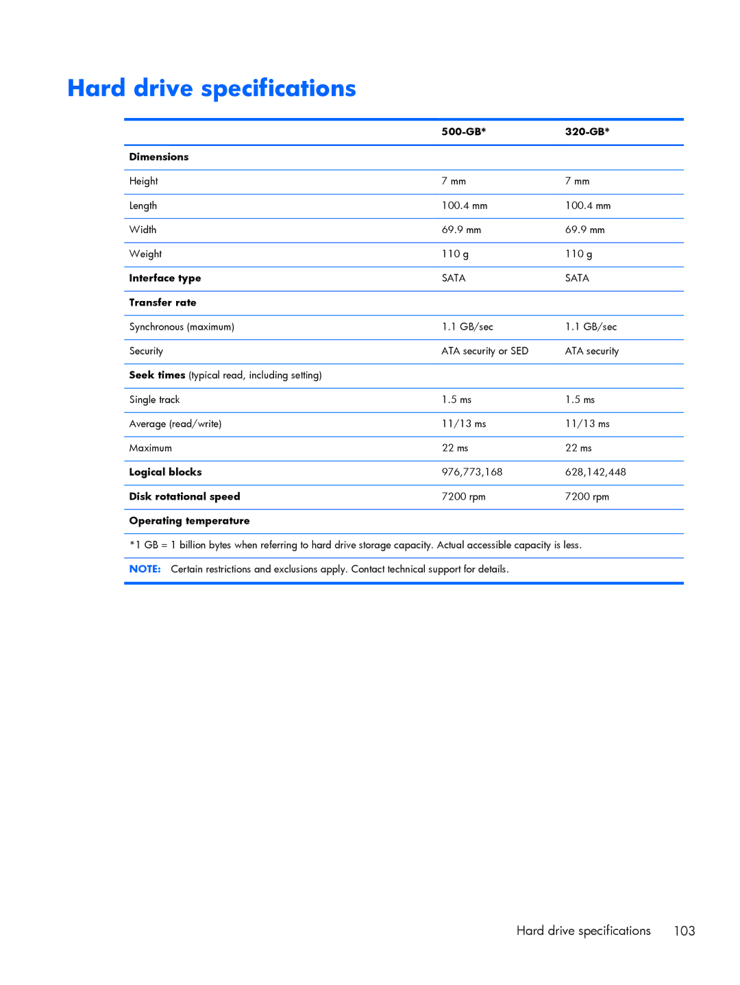
Dimensions
Operating temperature
Solid-state drive specifications
Dimensions
Access times
Operating temperature
mSATA drive specifications
Dimensions
Access times
7 Backup and recovery
Windows 7 - Backup and recovery
Creating recovery media with HP Recovery Disc Creator
Creating recovery media
Backing up your information
2. Select Driver DVD or Windows DVD
1. Select Start All Programs Maintenance Backup and Restore
Performing a system recovery
Using the Windows recovery tools
1. Select Start All Programs Maintenance Backup and Restore
4. Select Startup Repair
Using f11 recovery tools
Windows 8 - Backup and recovery
Using a Windows 7 operating system DVD purchased separately
6. Select Repair your computer
Backing up your information
Performing a system recovery
and Support
Using the Windows recovery tools
Using f11 recovery tools
Using Windows Refresh for quick and easy recovery
Using Windows 8 operating system media purchased separately
Remove everything and reinstall Windows
2. Click Settings
2. Click Settings
Using HP Software Setup
Backing up your information
SUSE Linux - Backup and recovery
Creating backups
1. Select Computer More Applications Tools Backup Manager Restore
Performing a system recovery
USB Recovery option
Restore?
1. Select Computer More Applications
2. Select Computer More applications Tools Create Recovery USB
Remove everything and reinstall SLED
8 Statement of Volatility
h. Select the File menu, then Save Changes and Exit
a. Hard Disk Drive HDD
b. Solid State Drive SSD
Non Volatile
Non-volatile memory usage
What is the
power is
Amount
What is the
power is
Non Volatile
Questions and answers
Requirements for all countries
9 Power cord set requirements
Accredited agency
Requirements for specific countries and regions
126 Chapter 9 Power cord set requirements
Country/region
Battery
10 Recycling
Display
Perform the following steps to disassemble the display assembly
3. Remove the display bezel
128 Chapter 10 Recycling
6. Remove the display panel assembly 2 from the display enclosure
7. Position the display panel assembly upside-down
Display
14. Position the display panel right-side up
10. Remove the display panel frame 2 from the display panel
12. Lift the top edge of the backlight cover 2 and swing it outward
13. Remove the backlight cover
16. Position the display panel upside-down
17. Remove the backlight frame from the display panel
Display
23. Remove the LCD panel 24. Recycle the LCD panel and backlight
18. Remove the backlight from the backlight frame
19. Disconnect the display panel cable 1 from the LCD panel
21. Release the LCD panel 3 from the display rear panel
Index
Page
chipset
Ethernet
flash cache