b.Remove the display bezel (4). The display bezel is available using spare part number
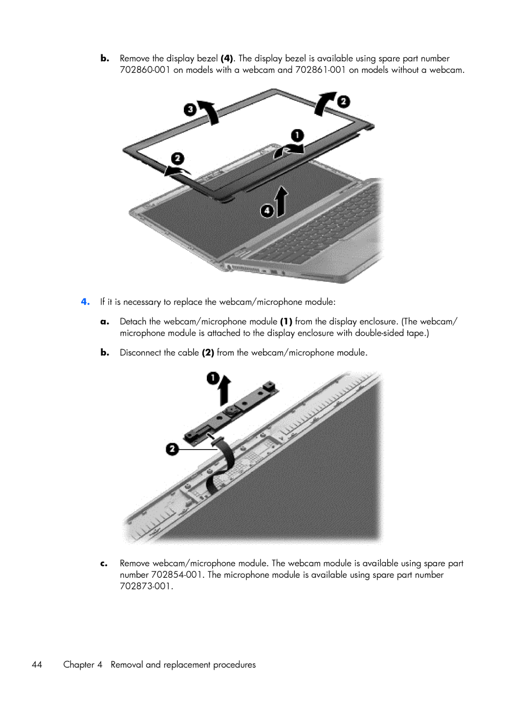
4.If it is necessary to replace the webcam/microphone module:
a.Detach the webcam/microphone module (1) from the display enclosure. (The webcam/ microphone module is attached to the display enclosure with
b.Disconnect the cable (2) from the webcam/microphone module.
c.Remove webcam/microphone module. The webcam module is available using spare part number
44 | Chapter 4 Removal and replacement procedures |