After selecting the coaxial switch or attenuator, install as follows:
1.Position the coaxial switch or attenuator behind the panel
2.Route the ribbon cable from the Microwave Switch or Attenuator to the
3.Install the correct filler panel on the switch so that minimal air can flow through the slot.
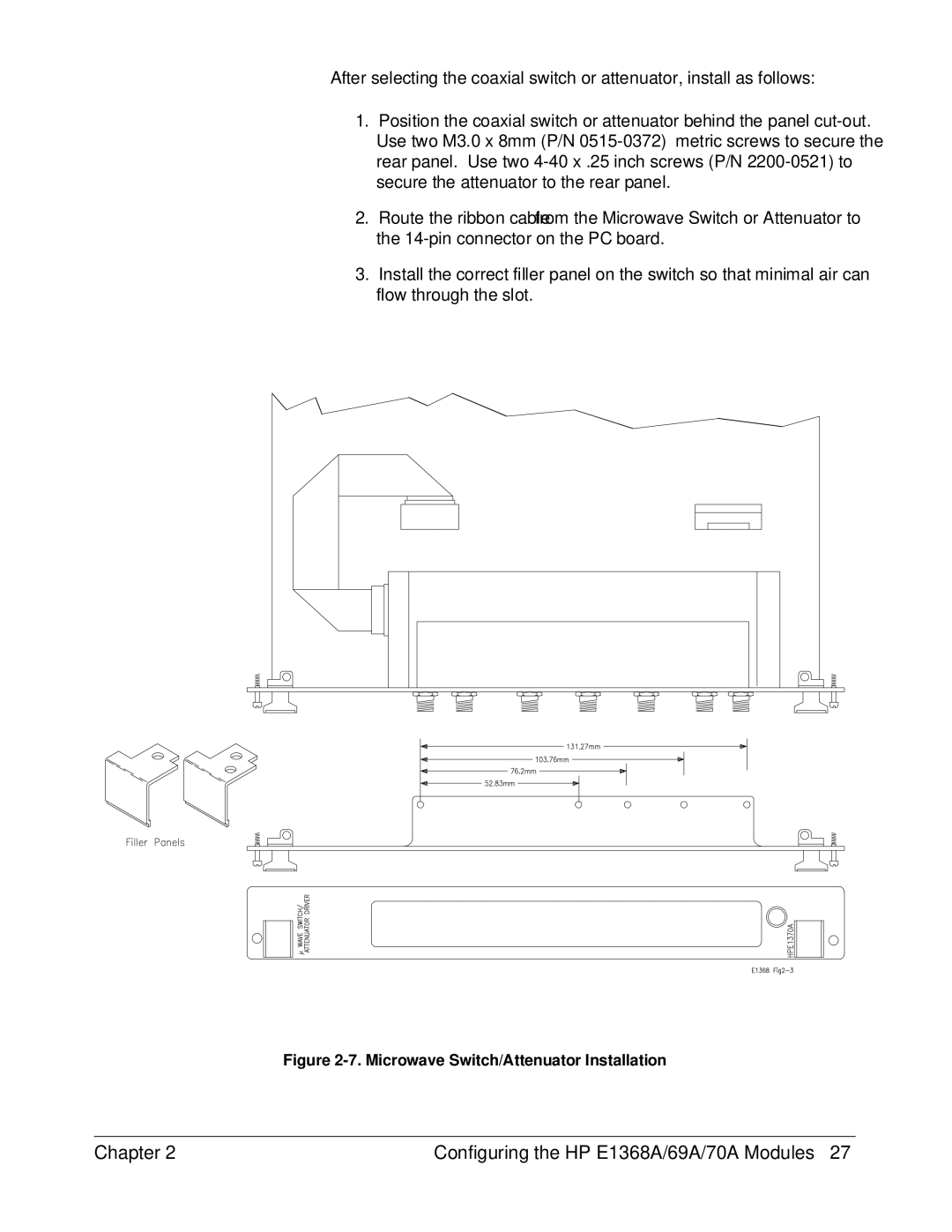
Figure 2-7. Microwave Switch/Attenuator Installation
Chapter 2 | Configuring the HP E1368A/69A/70A Modules 27 |