Example: 4 x 1 Multiplexer
This example shows how to configure the HP E1368A Microwave Switch to select one of four signals for output. For the example, all three switches (channels 00 through 02) will be used. Figure
To route signal "A" to the output, execute:
OPEN (@100,102) | Connects signal "A" (channel 00 |
| port 1) to the output (channel 02 |
| port C). |
To route signal "B" to the output, execute:
CLOS (@100);OPEN (@102) | Connects signal "B" (channel 00 |
| port 2) to the output (channel 02 |
| port C). To route signal "C" to the |
| output, execute: |
OPEN (@101);CLOS (@102) | Connects signal "C" (channel 01 |
| port 1) to the output (channel 02 |
| port C). |
To route signal "D" to the output, execute: |
|
CLOS (@101,102) | Connects signal "D" (channel 01 |
| port 2) to the output (channel 02 |
| port C). |
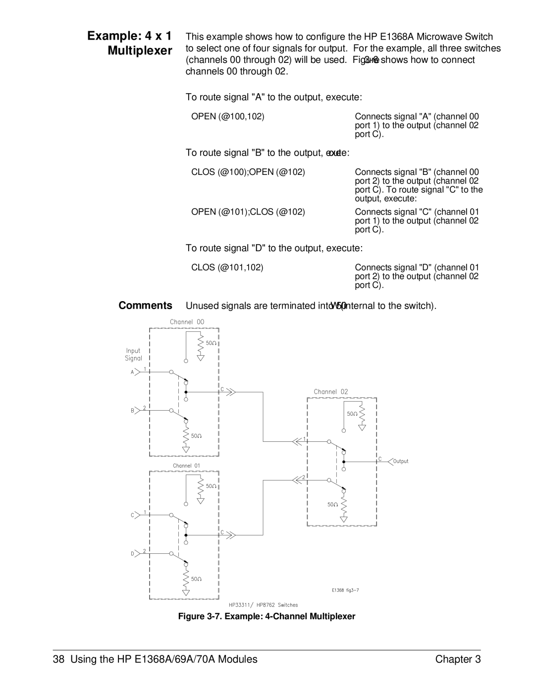
Comments Unused signals are terminated into 50Ω (internal to the switch).
Figure 3-7. Example: 4-Channel Multiplexer
38 Using the HP E1368A/69A/70A Modules | Chapter 3 |