Selecting the Interrupt Priority
The Microwave Switch modules generate interrupts after a channel has been closed or opened. These interrupts are sent to, and acknowledgments are received from, the slot 0 module via the VXIbus backplane interrupt lines.
For most applications where the Microwave Switch modules are installed in an HP 75000 Series B or Series C mainframe, these jumpers do not have to be moved. This is because the VXIbus interrupt lines have the same priority and interrupt priority is established by installing modules in slots numerically closest to the slot 0 module. Thus, slot 1 (internal to the Series B mainframe) has a higher priority than slot 2 (also internal), slot 2 has a higher priority than slot 3, etc.
Refer to Figure
Note Both jumper locations must have the same interrupt priority level jumper installed. Changing the priority level jumpers is not recommended. Do not change unless specifically instructed to do so.
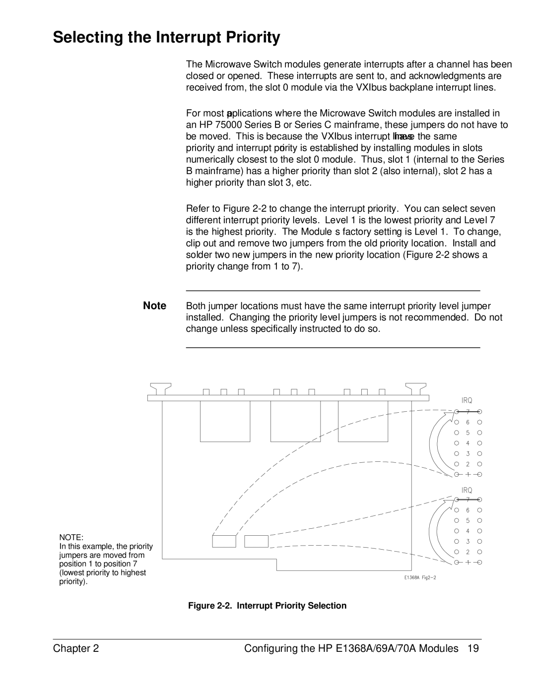
NOTE:
In this example, the priority jumpers are moved from position 1 to position 7 (lowest priority to highest priority).
Figure 2-2. Interrupt Priority Selection
Chapter 2 | Configuring the HP E1368A/69A/70A Modules 19 |