Connecting
Switches External
to the Module
Caution
Connection of up to five coaxial switches (channels
The maximum current that the control circuit can accommodate is 1 amp per switch. Maximum current also depends on the output capacity of the mainframe or power supply used.
After selecting the coaxial switches, connect to the
1.Route an
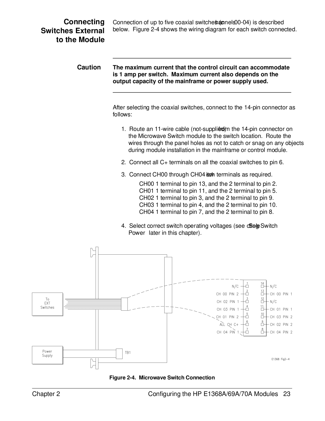
2.Connect all C+ terminals on all the coaxial switches to pin 6.
3.Connect CH00 through CH04 switch terminals as required.
CH00 1 terminal to pin 13, and the 2 terminal to pin 2.
CH01 1 terminal to pin 11, and the 2 terminal to pin 5.
CH02 1 terminal to pin 3, and the 2 terminal to pin 9.
CH03 1 terminal to pin 4, and the 2 terminal to pin 10.
CH04 1 terminal to pin 7, and the 2 terminal to pin 8.
4.Select correct switch operating voltages (see “ Sele cting Switch Power” later in this chapter).
Figure 2-4. Microwave Switch Connection
Chapter 2 | Configuring the HP E1368A/69A/70A Modules 23 |