STATus
| The STATus subsystem reports the bit values of the Operation Status |
| Register. Only bit 8 in the Standard Operation Status Register is used to |
| notify that a scan is complete. |
Subsystem Syntax | STATus |
| :OPERation |
| :ENABle <number> |
| :ENABle? |
| [:EVENt]? |
The STATus system contains four registers, two of which are under IEEE
488.2control. These are the Standard Event Status Register (*ESE) and the Status Byte Register (*STB?). Refer to the appropriate mainframe or command module operating manual for more information on these registers.
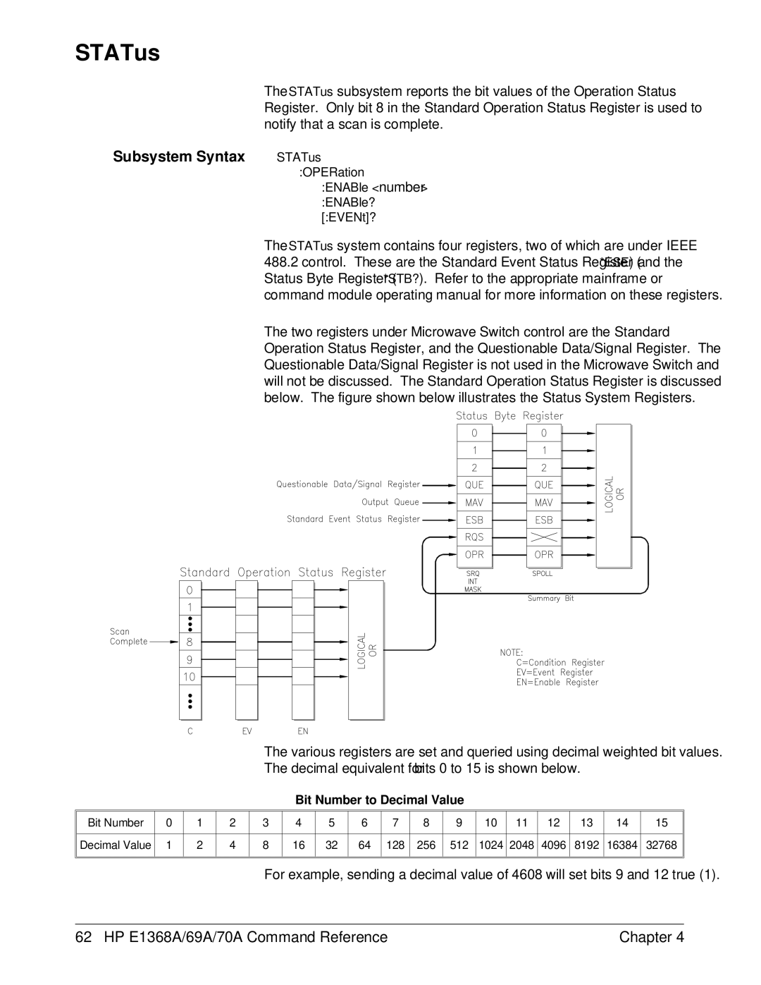
The two registers under Microwave Switch control are the Standard Operation Status Register, and the Questionable Data/Signal Register. The Questionable Data/Signal Register is not used in the Microwave Switch and will not be discussed. The Standard Operation Status Register is discussed below. The figure shown below illustrates the Status System Registers.
The various registers are set and queried using decimal weighted bit values.
The decimal equivalent for bits 0 to 15 is shown below.
Bit Number to Decimal Value
Bit Number | 0 | 1 | 2 | 3 | 4 | 5 | 6 | 7 | 8 | 9 | 10 | 11 | 12 | 13 | 14 | 15 |
|
|
|
|
|
|
|
|
|
|
|
|
|
|
|
|
|
Decimal Value | 1 | 2 | 4 | 8 | 16 | 32 | 64 | 128 | 256 | 512 | 1024 | 2048 | 4096 | 8192 | 16384 | 32768 |
|
|
|
|
|
|
|
|
|
|
|
|
|
|
|
|
|
|
|
|
|
|
|
|
|
|
|
|
|
|
|
|
|
|
For example, sending a decimal value of 4608 will set bits 9 and 12 true (1).
62 HP E1368A/69A/70A Command Reference | Chapter 4 |