Replacing IRU Components
3.A line will be added to the L1 system controller’s log file indicating the fan warning.
4.If ESP is used, a warning message will be sent to it also, (see “SGI Electronic Support” on page 149).
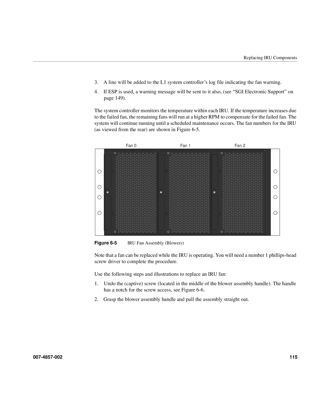
The system controller monitors the temperature within each IRU. If the temperature increases due to the failed fan, the remaining fans will run at a higher RPM to compensate for the failed fan. The system will continue running until a scheduled maintenance occurs. The fan numbers for the IRU (as viewed from the rear) are shown in Figure
Fan 0 | Fan 1 | Fan 2 |
Figure 6-5 IRU Fan Assembly (Blowers)
Note that a fan can be replaced while the IRU is operating. You will need a number 1
Use the following steps and illustrations to replace an IRU fan:
1.Undo the (captive) screw (located in the middle of the blower assembly handle). The handle has a notch for the screw access, see Figure
2.Grasp the blower assembly handle and pull the assembly straight out.
115 |
