Ethernet Switch
The front panel display contains the following items:
•2 x 12 character liquid crystal display (LCD). The display identifies the IRU, shows system status, warns of required service, and identifies a failed component.
•Power (On/Off) button (insert paper clip to actuate) and power on LED.
•Service required LED.
•Failure LED.
•Reset switch (insert paper clip to actuate).
•
Note: The reset and NMI switch functions on any IRU in a NUMAlink connected system will affect all the IRUs in the system.
Ethernet Switch
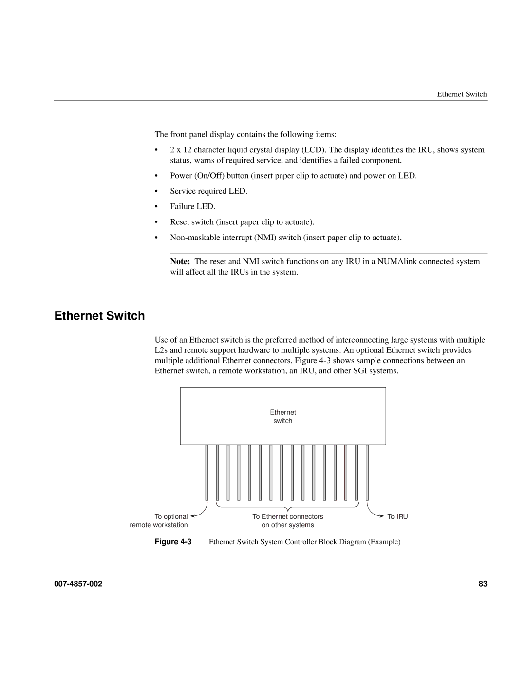
Use of an Ethernet switch is the preferred method of interconnecting large systems with multiple L2s and remote support hardware to multiple systems. An optional Ethernet switch provides multiple additional Ethernet connectors. Figure
Ethernet
switch
To optional | To Ethernet connectors | To IRU |
remote workstation | on other systems |
|
Figure 4-3 Ethernet Switch System Controller Block Diagram (Example)
83 |