Manuals
/
Brands
/
Computer Equipment
/
Switch
/
Intel
/
Computer Equipment
/
Switch
Intel
SGI Altix 450
- page 91
1
91
198
198
Download
198 pages, 8.04 Mb
System Models
007-4857-002
69
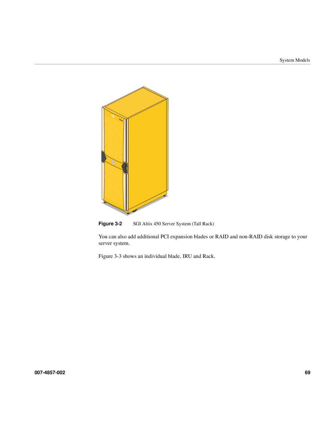
Figure 3-2
SGI Altix 450 Server System (Tall Rack)
You can also add additional PCI expansion blades or RAID and non-RAID disk storage to your
server system.
Figure
3-3 shows an individu
al blade, IRU and Rack.
Contents
Main
Page
Page
Page
Contents
Page
Page
Page
Page
Page
List of Figures
Page
Page
Page
List of Tables
Page
About This Guide
Audience
Important Information
Warning:
Chapter Descriptions
Related Publications
Page
Conventions
Product Support
Reader Comments
1. System Installation
System Installation Overview
Safety Precautions
Hazard Statements
Warning:
ESD Precautions
Safety Measures
Warning:
Installing a Rack
Preinstallation Activities
Tools Required
Table1-1 lists the tools that you need to complete the installation.
Page
Page
Page
Page
Unloading and Moving System Equipment
Warning:
Page
Page
Page
Removing a Short Rack from the Shipping Crate
Warning:
Page
Unpacking and Installing the Tall Rack
Warning:
Page
Page
Positioning and Leveling Racks
Unpacking and Inspecting Modules
Page
Installing the IRUs in a Rack
Determining Space Requirements
Determining Where to Attach Rails in a Rack
Rackmounting IRUs with Shelf Rails
Page
Removing a Rackmounted IRU Module
Warning:
NUMAlink Cabling the System IRUs
Page
Cabling the System IRUs to a Power Source
Connecting an IRU Module to a Power Source (No Rack)
Page
Page
Connecting System Modules to a Rack Power Source
Page
Connecting the System Console
Page
Operating Your System
Powering the System On and Off
Page
Page
Page
Page
Page
L1 Front Panel Controls
Operating the L1 Controller
Page
2. Operation Procedures
Precautions
ESD Precaution
Page
System Controller Network
Console Connections
Connecting to the System Controller
Communicating with the System Controller
Powering the System On and Off
Preparing to Power On
Page
Powering On and Off at the Console
Page
Using Embedded Support Partner (ESP)
Monitoring Your Server
2D Graphics Video Interface
Installing Optional Components
Warning:
I/O Blade Overview
Adding or Removing Disk Drives
Reconfigure the System Disk Drive(s) for RAID 1
Page
Page
Page
Page
Page
3. System Overview
System Models
Page
System Architecture
Page
System Features
Modularity and Scalability
Distributed Shared Memory (DSM)
Distributed Shared I/O
ccNUMA Architecture
Reliability, Availability, and Serviceability (RAS)
Page
System Components
System Components
007-4857-002 77
Figure 3-5 Altix 450 IRU System Components Example
Bay (Unit) Numbering
Rack Numbering
Page
4. System Control
Levels of System Control
System Controller Interaction
L1 Controller
L1 Controller Functions
L1 Front Panel Display
Ethernet Switch
Console Hardware Requirements
Operating the L1
L1 Mode
Page
Console Mode from L1
Page
L2 Operation
Configuring an L2s IP Address
Page
Viewing System Configuration
Setting Command Targeting
Page
Viewing Information, Warnings, and Error Messages
Powering On, Powering Off, and Resetting the System From the L2
Console Mode from the L2
Console Selection
Page
L1 Mode From L2
Upgrading L1 Firmware
Page
5. Rack Information
Overview
Altix 42U and 20U Rack Features
Page
Technical Specifications
Table5-1 lists the technical specifications of the Altix 450 tall rack.
Table5-2 lists the technical specifications of the Altix 450 short rack.
Page
Page
6. Maintenance and Upgrade Procedures
Maintenance Precautions and Procedures
Preparing the System for Maintenance or Upgrade
Returning the System to Operation
Installing or Removing Internal Parts
Replacing IRU Components
Remove and Replace the System Control Display Panel
AB
C
Page
Removing or Adding IRU Power Supplies
Removing and Replacing IRU Fans (Blowers)
Page
Page
Page
Removing or Replacing a System Blade From the IRU
Removing and Replacing a Compute/Memory Blade
Page
Page
Memory DIMM Group Placement and Guidelines
122 007-4857-002
6: Maintenance and Upgrade Procedures
Figure6-10 DIMM Group Locations Diagram
Remove and Replace the DVD Drive
Page
Page
Page
Overview of PCI Express Operation
Adding or Replacing PCI/PCI-X Cards
Warning:
Installing PCI Cards in the Three-Slot Blade
Page
Page
Page
Page
Page
Page
Add or Remove a PCI Card in Base IA Blades
Page
138 007-4857-002
6: Maintenance and Upgrade Procedures
Figure6-26 Location of Disk Drive Bays on IA/IA2 Blade
Installing or Replacing a Disk Drive in the IA Blade
Removing a System Disk Drive
Installing a System Disk Drive
Page
Page
Page
Troubleshooting Chart
L1 Controller Error Messages
Page
LED Status Indicators
IRU Power Supply LEDs
IRU NUMAlink Router Port LEDs
Compute/Memory Blade LEDs
SGI Electronic Support
Page
Page
Page
A. Technical Specifications and Pinouts
System-level Specifications
Physical Specifications
TableA-2 shows the physical specifications of the Altix 450 system in a 42U rack.
TableA-3 on page 155 lists the physical specifications of the Altix 450 system in a 20U rack.
Page
Environmental Specifications
.
Power Specifications
TableA-6 shows the power specifications for the system.
Page
Ethernet Port
160 007-4857-002
A: Technical Specifications and Pinouts
Figure A-2 Serial Port Connector
Serial Ports
TableA-8 shows pinout assignments for the 9-pin male DB-9 connector.
External SAS/SATA Port Connector
USB Type A Connector
Page
B. Safety Information and Regulatory Specifications
Safety Information
Page
Regulatory Specifications
CMN Number
CE Notice and Manufacturers Declaration of Conformity
Electromagnetic Emissions
Page
Shielded Cables
Electrostatic Discharge
Page
Page
Index