VIS-CAM System
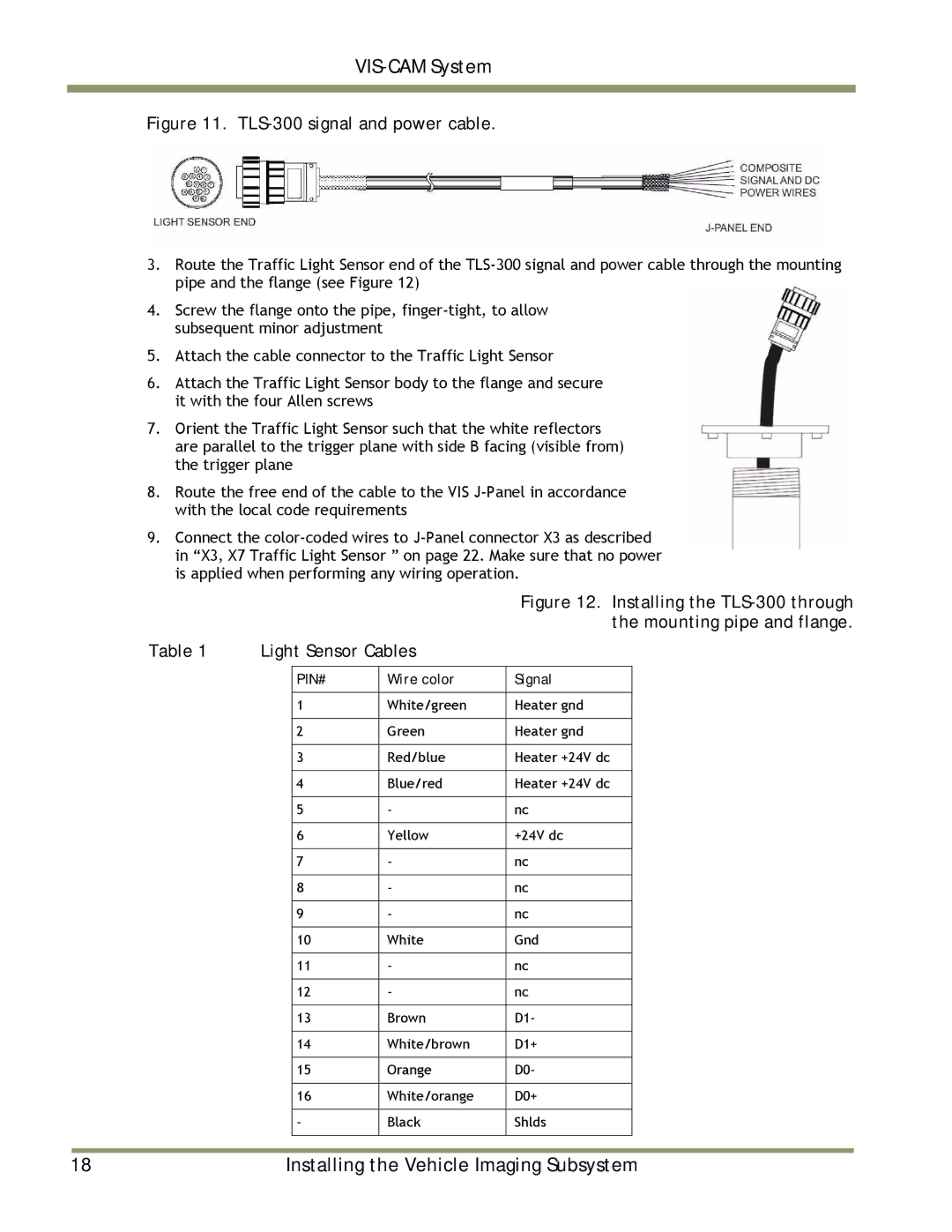
Figure 11. TLS-300 signal and power cable.
3.Route the Traffic Light Sensor end of the
4.Screw the flange onto the pipe,
5.Attach the cable connector to the Traffic Light Sensor
6.Attach the Traffic Light Sensor body to the flange and secure it with the four Allen screws
7.Orient the Traffic Light Sensor such that the white reflectors are parallel to the trigger plane with side B facing (visible from) the trigger plane
8.Route the free end of the cable to the VIS
9.Connect the
|
|
|
| Figure 12. Installing the | |
|
|
|
| the mounting pipe and flange. | |
Table 1 | Light Sensor Cables |
|
| ||
|
|
|
|
|
|
|
| PIN# | Wire color | Signal |
|
|
|
|
|
|
|
|
| 1 | White/green | Heater gnd |
|
|
|
|
|
|
|
|
| 2 | Green | Heater gnd |
|
|
|
|
|
|
|
|
| 3 | Red/blue | Heater +24V dc |
|
|
|
|
|
|
|
|
| 4 | Blue/red | Heater +24V dc |
|
|
|
|
|
|
|
|
| 5 | - | nc |
|
|
|
|
|
|
|
|
| 6 | Yellow | +24V dc |
|
|
|
|
|
|
|
|
| 7 | - | nc |
|
|
|
|
|
|
|
|
| 8 | - | nc |
|
|
|
|
|
|
|
|
| 9 | - | nc |
|
|
|
|
|
|
|
|
| 10 | White | Gnd |
|
|
|
|
|
|
|
|
| 11 | - | nc |
|
|
|
|
|
|
|
|
| 12 | - | nc |
|
|
|
|
|
|
|
|
| 13 | Brown | D1- |
|
|
|
|
|
|
|
|
| 14 | White/brown | D1+ |
|
|
|
|
|
|
|
|
| 15 | Orange | D0- |
|
|
|
|
|
|
|
|
| 16 | White/orange | D0+ |
|
|
|
|
|
|
|
|
| - | Black | Shlds |
|
|
|
|
|
|
|
|
|
|
|
|
|
18 | Installing the Vehicle Imaging Subsystem |