VIS-CAM System
5.2X4: I/O Board Connection to J-panel
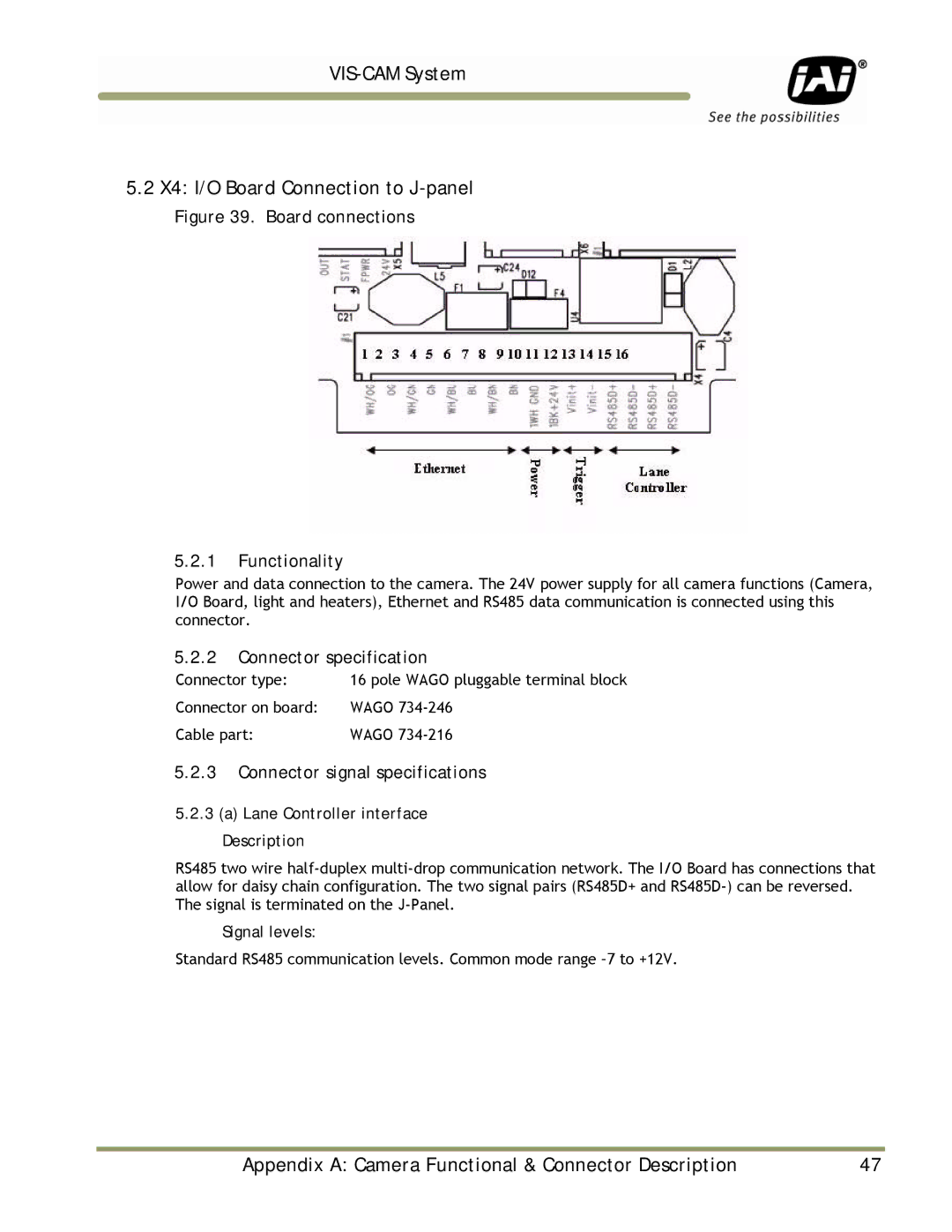
Figure 39. Board connections
5.2.1Functionality
Power and data connection to the camera. The 24V power supply for all camera functions (Camera, I/O Board, light and heaters), Ethernet and RS485 data communication is connected using this connector.
5.2.2Connector specification
Connector type: | 16 pole WAGO pluggable terminal block |
Connector on board: | WAGO |
Cable part: | WAGO |
5.2.3Connector signal specifications
5.2.3(a) Lane Controller interface Description
RS485 two wire
Signal levels:
Standard RS485 communication levels. Common mode range
Appendix A: Camera Functional & Connector Description | 47 |