VIS-CAM System
5.6.4Connector physical Interface
Ethernet test connections.
Pin | Signal | Description | Connection to | Remarks |
|
|
|
|
|
1 | A+ (wh/org) | Ethernet A+ | Gigabit switch | Connected when testing |
|
|
|
|
|
2 | A- (org) | Ethernet A- | Gigabit switch | Connected when testing |
|
|
|
|
|
3 | B+ (wht/grn) | Ethernet B+ | Gigabit switch | Connected when testing |
|
|
|
|
|
4 | Nu (wht/blu) | Not used | — | — |
|
|
|
|
|
5 | Nu (blu) | Not used | — | — |
|
|
|
|
|
6 | B- (grn) | Ethernet B- | Gigabit switch | Connected when testing |
|
|
|
|
|
7 | Nu (wht/brn) | Not used | — | — |
|
|
|
|
|
8 | Nu (brn) | Not used | — | — |
|
|
|
|
|
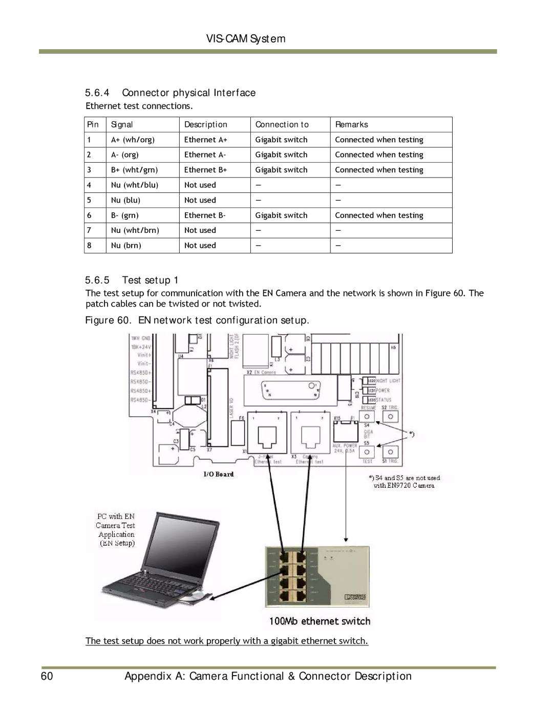
5.6.5Test setup 1
The test setup for communication with the EN Camera and the network is shown in Figure 60. The patch cables can be twisted or not twisted.
Figure 60. EN network test configuration setup.
The test setup does not work properly with a gigabit ethernet switch.
|
|
|
60 | Appendix A: Camera Functional & Connector Description | |