VIS-CAM System
6.2.3 (c) Ethernet Interface
100 Mb Ethernet interface. The signals are routed directly to RJ45 connector X11. The cable to the camera must be a Cat 5e or preferably a Cat 6 cable. The wire color marking on the PCB uses standard Ethernet wire colors.
6.2.3 (d) Power output |
|
Voltage | 24VDC from power supply connected to X6 or X7 |
Current | 2A fused |
6.2.4Connector physical Interface
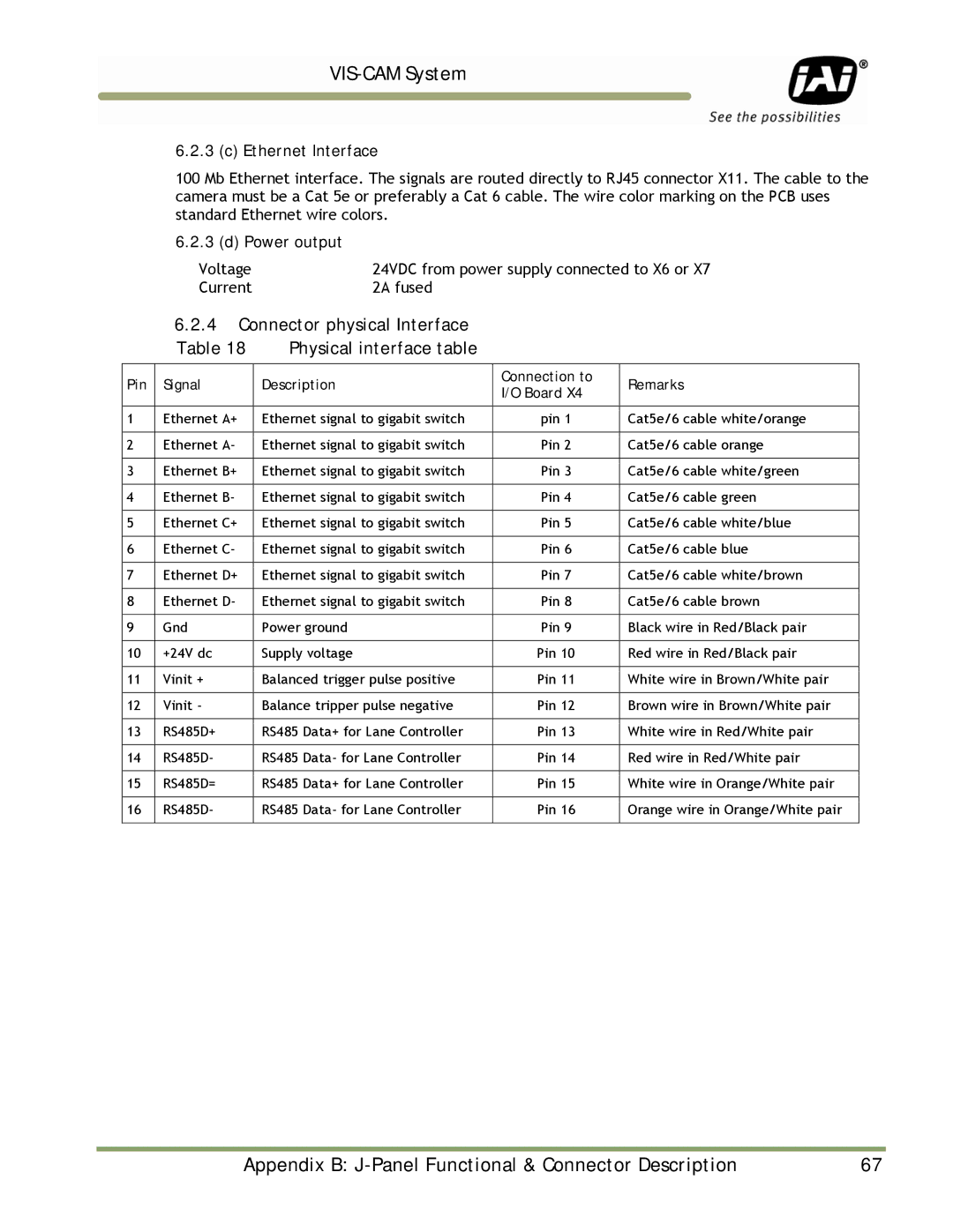
Table 18 Physical interface table
Pin | Signal | Description | Connection to | Remarks | |
I/O Board X4 | |||||
|
|
|
| ||
|
|
|
|
| |
1 | Ethernet A+ | Ethernet signal to gigabit switch | pin 1 | Cat5e/6 cable white/orange | |
|
|
|
|
| |
2 | Ethernet A- | Ethernet signal to gigabit switch | Pin 2 | Cat5e/6 cable orange | |
|
|
|
|
| |
3 | Ethernet B+ | Ethernet signal to gigabit switch | Pin 3 | Cat5e/6 cable white/green | |
|
|
|
|
| |
4 | Ethernet B- | Ethernet signal to gigabit switch | Pin 4 | Cat5e/6 cable green | |
|
|
|
|
| |
5 | Ethernet C+ | Ethernet signal to gigabit switch | Pin 5 | Cat5e/6 cable white/blue | |
|
|
|
|
| |
6 | Ethernet C- | Ethernet signal to gigabit switch | Pin 6 | Cat5e/6 cable blue | |
|
|
|
|
| |
7 | Ethernet D+ | Ethernet signal to gigabit switch | Pin 7 | Cat5e/6 cable white/brown | |
|
|
|
|
| |
8 | Ethernet D- | Ethernet signal to gigabit switch | Pin 8 | Cat5e/6 cable brown | |
|
|
|
|
| |
9 | Gnd | Power ground | Pin 9 | Black wire in Red/Black pair | |
|
|
|
|
| |
10 | +24V dc | Supply voltage | Pin 10 | Red wire in Red/Black pair | |
|
|
|
|
| |
11 | Vinit + | Balanced trigger pulse positive | Pin 11 | White wire in Brown/White pair | |
|
|
|
|
| |
12 | Vinit - | Balance tripper pulse negative | Pin 12 | Brown wire in Brown/White pair | |
|
|
|
|
| |
13 | RS485D+ | RS485 Data+ for Lane Controller | Pin 13 | White wire in Red/White pair | |
|
|
|
|
| |
14 | RS485D- | RS485 Data- for Lane Controller | Pin 14 | Red wire in Red/White pair | |
|
|
|
|
| |
15 | RS485D= | RS485 Data+ for Lane Controller | Pin 15 | White wire in Orange/White pair | |
|
|
|
|
| |
16 | RS485D- | RS485 Data- for Lane Controller | Pin 16 | Orange wire in Orange/White pair | |
|
|
|
|
|
Appendix B: | 67 |
