VIS-CAM System
Electrical interface on the I/O board:
Figure 40. Interface drawing.
5.2.3 (b) Trigger input Description
The trigger input is balanced and the input circuit is a RS485 receiver.
Signal levels
The signal levels are standard RS485 signals. The specification below is taken from Linear Technologies datasheet for LTC1480:
The common mode range is
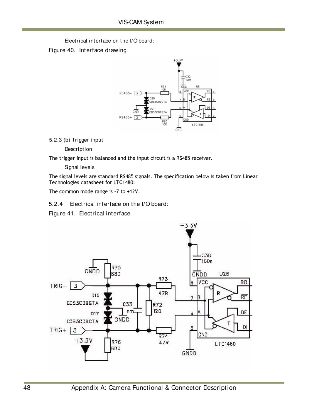
5.2.4Electrical interface on the I/O board: Figure 41. Electrical interface
|
|
|
48 | Appendix A: Camera Functional & Connector Description | |