VIS-CAM System
6.4.2Connector specification
Connector type: | 6 pole WAGO pluggable terminal block |
Connector on board: | WAGO |
Cable part: | WAGO |
6.4.3Connector signal specifications
6.4.3 (a) Power output
Voltage: | 24V DC from power supply connected to X6 or X7 |
Current: | 2A fused |
6.4.3 (b) Databus D0 and D1
D0 and D1 are RS485 databus signals from the light sensor.
6.4.4Connector physical Interface
Table 25 Physical interface connections
Pin | Signal | Description | Connection to |
|
|
|
|
1 | 24V dc | Power output |
|
|
|
|
|
2 | Gnd | Power return |
|
|
|
|
|
3 | D0+ | RS485 databus D0+ |
|
|
|
|
|
4 | D0- | RS485 databus D0- |
|
|
|
|
|
5 | D1+ | RS485 databus D1+ |
|
|
|
|
|
6 | D1- | RS485 databus D1+ |
|
|
|
|
|
6.4.5Indicators
There are two LED indicators mounted at the connector:
Table 26 | LED physical indicators |
| ||
|
|
|
|
|
| LED label | LED color |
| Indication |
|
|
|
|
|
| Power | Green |
| 24V present at connector 1 |
|
|
|
|
|
|
| red |
| No 24V at connector pin 1 |
|
|
|
|
|
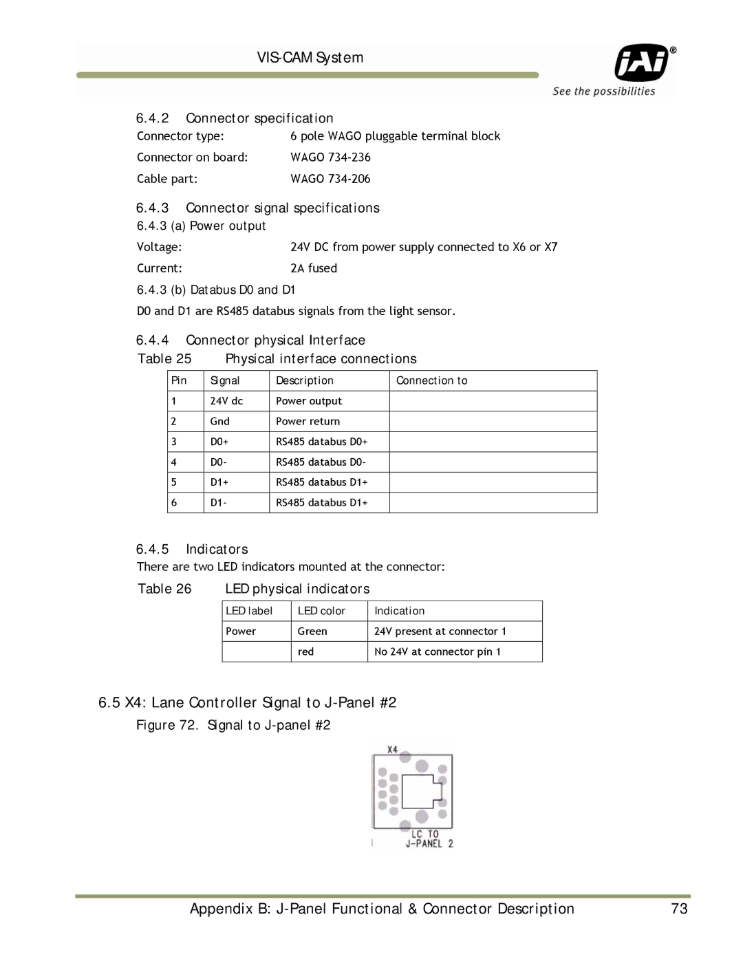
6.5X4: Lane Controller Signal to J-Panel #2
Figure 72. Signal to J-panel #2
Appendix B: | 73 |