VIS-CAM System
6.6.3Connector signal specifications
6.6.3 (a) Data signal
RS485 databus signals from a Lane Controller connected to another
Table 28 Physical pin connections J-panel #1.
Pin | Signal | Description | Connection to |
|
|
|
|
1 | RS485+ | RS485 databus D+ |
|
|
|
|
|
2 | RS485- | RS485 databus D- |
|
|
|
|
|
3 | - | NC |
|
|
|
|
|
4 | - | NC |
|
|
|
|
|
5 | - | NC |
|
|
|
|
|
6 | - | NC |
|
|
|
|
|
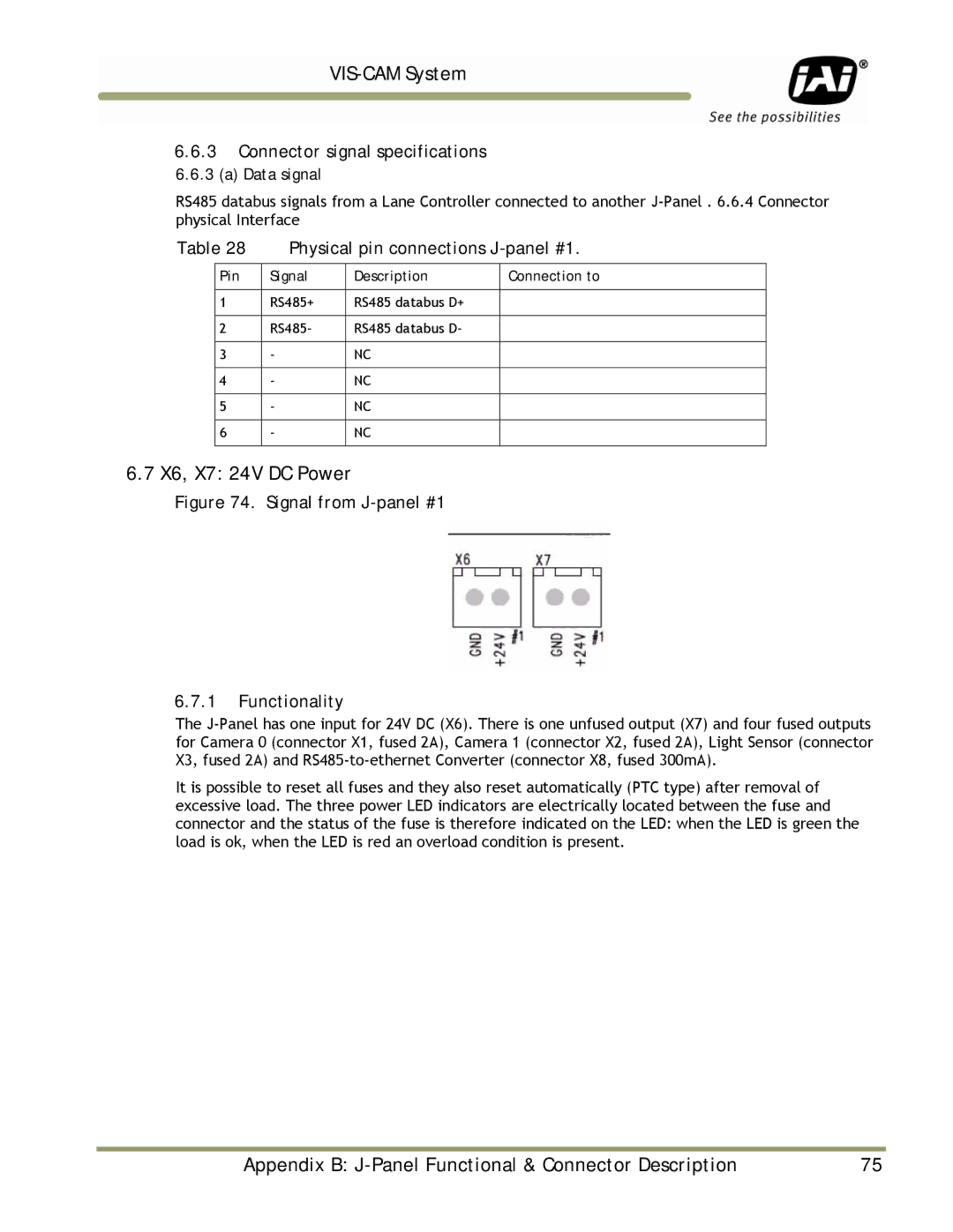
6.7 X6, X7: 24V DC Power
Figure 74. Signal from J-panel #1
6.7.1Functionality
The
It is possible to reset all fuses and they also reset automatically (PTC type) after removal of excessive load. The three power LED indicators are electrically located between the fuse and connector and the status of the fuse is therefore indicated on the LED: when the LED is green the load is ok, when the LED is red an overload condition is present.
Appendix B: | 75 |