VIS-CAM System
6.5.1Functionality
Lane Controller RS485 signal to a second
6.5.2Connector specification
Connector type: | 8 pole shielded RJ45 |
Connector on board: | Taitek/Kinsun |
Cable part: | Standard RJ45 connector |
6.5.3Connector signal specifications
Datasignal
RS485 databus signals from the Lane Controller.
6.5.4Connector physical Interface
Table 27 Physical connector table for
Pin | Signal | Description | Connection to |
|
|
|
|
1 | RS485+ | RS485 databus D+ |
|
|
|
|
|
2 | RS485- | RS485 databus D- |
|
|
|
|
|
3 | - | NC |
|
|
|
|
|
4 | - | NC |
|
|
|
|
|
5 | - | NC |
|
|
|
|
|
6 | - | NC |
|
|
|
|
|
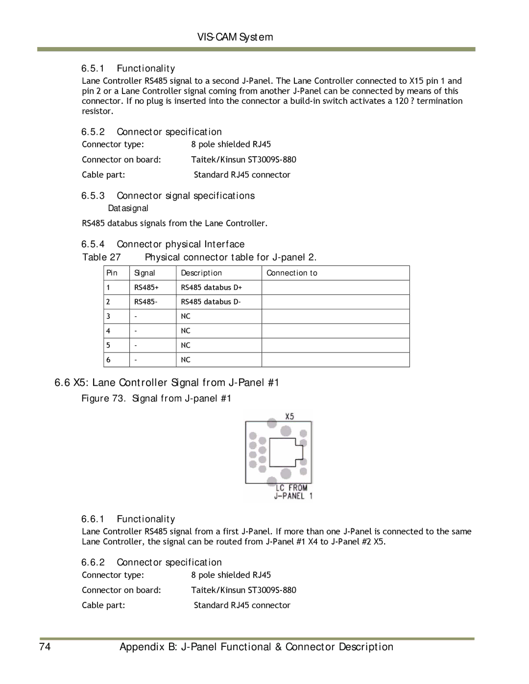
6.6X5: Lane Controller Signal from J-Panel #1
Figure 73. Signal from J-panel #1
6.6.1Functionality
Lane Controller RS485 signal from a first
6.6.2Connector specification
Connector type: | 8 pole shielded RJ45 |
Connector on board: | Taitek/Kinsun |
Cable part: | Standard RJ45 connector |
|
|
|
74 | Appendix B: | |