FS-1920
Regarding Tradenames
Limitation of Remedies
Limited Warranty
License
General
Typeface Trademark Acknowledgement
Agfa Japan License Agreement
Contents
Contents
Maintenance
Paper Selection
Appendix a Options
Troubleshooting
Fonts
Appendix B Host Computer Interface
Glossary Glossary-1 Index Index-1
Introduction
Features
Printer control language Prescribe
USB Universal Serial Bus Interface
MPS
KPDL3 Kyocera Printer Description Language
CompactFlash card slot for option fonts, macros, forms, etc
Snmp compliance
Support for network printer monitor utility KM-NET Viewer
For More Information
Description
Guide to the Operation Guide
Option
Using the Operator Panel
Understanding the Operator Panel
Message Display
Message Meaning
Interface Indicator
Paper Size Indicator
Message Paper Size Display
Indicator Description
Paper Type Indicator
READY, DATA, and Attention Indicators
Message Display Paper Type
Keys
Key Function
Over operator panel settings
Menu System Road Map
TCP/IP
IBM
KIR
A4/LT
Off Printer Reset Resource Prot Permanent Perm / Temp Buzzer
Print Menu Map
Printing Test Pages
Menu Map
Print Menu Map ?
Menu MAP
Sample Menu MAP
Status
Print Status
Print Status Page ?
Status
Software Version
Installation Options
Error Log
Hardware Information
Interface Information
KIR Test Pattern
Service Status
Service
Others
Network Card Interface Status
Opt. StatusPage ? Off
Opt. StatusPage ? On
Opt. StatusPage On
Font Select Internal
Font Lists
Font
List
Font Lists
Prescribe
Print HEX-DUMP?
Received Data Dumping
Print HEX-DUMP
Processing Waiting
Setting the Paper Size
Setting the Paper Size in Paper Cassette
Paper Handling
Paper Handling
Custom Paper Size
Cassette Size Custom
Unit mm
Unit ? mm
Dimension 216 mm
Dimension
Setting the Paper Size in MP Tray
MP Tray Size A4
MP Tray Size ? A4
Cassette Type Plain
Setting the Paper Type
Setting the Paper Type in Paper Cassette
Cassette Type ? Plain
Setting the Paper Type in MP Tray
MP Tray Type Plain
MP Tray Type ? Plain
Type Adjust Custom
Creating Custom Paper Type
Paper Handling
Paper Weight Normal
Paper Weight ? Normal
Setting the Paper Weight
Duplex path Enable
Duplex path ? Enable
Setting the Duplex Path
Reset Type Adjust
Reset Type Adjust ?
Resetting the Custom Paper Type
MP Tray Mode
MP Tray Mode Cassette
Feed Select Cassette
MP Tray Mode ? Cassette
Selecting the Paper Feed Source
Feed Select ? Cassette
Selecting the Output Stack
Stack Select Top tray FaceDn
Stack Select
Overriding A4 and Letter Size Difference
Override A4/LT Off
Override A4/LT ? Off
Emulation ?PCL
Pagination
Emulation
Changing the Emulation
Alt. Emulation ?PCL
Emulation
Emulation ?KPDL Auto
Alternative Emulation for Kpdl Emulation
Printing Kpdl Errors
?KPDL
Default font
Print Kpdl Errs ? On
Font
I000
?I000
Letter Description
Default Font Size
Size Points
Size
Courier Regular
Changing Type for Courier/Letter Gothic
Setting the Character Pitch for Courier/Letter Gothic
Pitch
Code Set
Code Set
Code Set ?IBM PC-8
Number of Copies
Set
Copies 001
Printing Orientation
Orientation Portrait
Orientation ? Portrait
KIR Kyocera Image Refinement
Status KIR Checking Lines
KIR Mode
KIR Mode ? On
Print Quality
EcoPrint Mode Off
EcoPrint Mode ? Off
Ecoprint
Resolution
Resolution Fast 1200 mode
Resolution
Mode Quick Copy Proof and Hold Private Print Stored Job
MPS
Job Retention
MPS
Printing Additional Copies using Quick Copy
Quick Copy
Job Storage
Quick Copy ?Arlen
Quick Copy Harold
Quick Copy ?Harold
Arlen ?Report
Deleting a Quick Copy Job
Report Delete
Proof and Hold
Printing Remaining Copies of a Proof and Hold Job
Quick Copy
Private/Stored ?Harold
Printing a Private Job
Private/Stored Harold
Private/Stored ?Arlen
Agenda Copies 001
Agenda
Agenda Copies
Agenda Delete
Printing a Stored Job
Releasing a Stored Job
Deleting a Stored Job
Printing a Code Job
KM-Net Job Manager
MPS
Printing a List of Code Jobs
List of Code JOB
List of Code JOB ?
Retrieving Jobs from Virtual Mailbox VMB
Print VMB Data Tray001
Tray001?
Printing a List of VMB
List of VMB
List of VMB ?
MPS Configuration
MPS Configuration
Temp. Code JOB Size 050MB
Maximum Space Assigned to Temporary Code Jobs
Perm. Code JOB Size 050MB
Size 05 0MB
Maximum Space Assigned to Permanent Code Jobs
VMB Size 050MB
VMB Size
Maximum Space Assigned to Virtual Mailboxes
Parallel Interface Mode
Interface
USB Interface Mode
Parallel I/F ? Auto
Interface ? USB
Serial Interface Parameters
Interface ? Serial
Parity None Protocol DTRpos.&XON
Baud Rate Data Bits
Stop Bits
Baud Rate
Network Interface Parameters
NetWare
EtherTalk Off Opt. StatusPage On
TCP/IP ? On TCP/IP On
Dhcp Off IP Address Subnet Mask Gateway 000.000.000.000
RAM Disk Mode Off
Operating the Storage Device
Activating the RAM Disk
RAM Disk Mode ? On
RAM Disk Size Mbyte
Read Data Data name
Reading Data
Memory Card
Read Data ?data name
Writing Data
Write Data
Write Data ?
Write Information
Deleting Data
Delete Data data name
Delete Data ?data name
Reading Fonts from a CompactFlash Card
Read Fonts
Read Fonts ?
Formatting a Storage Device
Format
Format ?
Printing a List of Data Names
List of Partitions
List Partitions ?
Partition List
Configuration
Protect Mode
Protect
Linefeed LF Action
Protect ? On
Protect ? Auto
LF Action LF only
Carriage-Return CR Action
CR Action CR only
CR Action ? CR only
Wide A4 Pitch
Wide A4 Off
Wide A4 ? Off
Print Density
Print Density
Total Printed Pages
Toner Counter Resetting
New Toner Installed
Life Counters
MSG Language English
New Toner Installed ?
Message Language
MSG Language ? English
Following order The key cycles in the reverse order
Automatic Form Feed Timeout
Form Feed Time Out 030sec
Sleep Timer Setting
Sleep Timer 015 min
Sleep Timer
Sleep Mode ? Off
Sleep Mode
Sleep Mode ? On
Turning Off the Sleep Timer
Printer Reset ?
Printer Resetting
Printer Reset
Self test Please wait Ready
Resource Protection
Resource Prot Off
Resource Prot ? Off
Alarm Buzzer Setting
Buzzer On
Buzzer ? On
Auto Continue Setting
Auto Continue Mode On
Auto Continue Mode ? On
Timer
Setting the Auto Continue Recovery Time
Auto Continue
Duplex Off
Duplex Printing Error Detection Setting
Finishing Error
Duplex ? Off
Paper Selection
General Guidelines
Paper Specifications
Specification
Paper Availability
Selecting the Right Paper
Condition of the Paper
Composition
Smoothness
Basis Weight
Paper Size
Multi-purpose Size Cassette or Tray
Bond Weight lb Europe Metric
Paper Weight Equivalence Table
Moisture Content
Weight g/m²
Paper Grain
Other Paper Properties
Special Paper
Transparency Overhead Projection Film
Paper type Media type
Adhesive-Backed Labels
Postcards
Envelopes
Thick Paper
Colored Paper
Preprinted Paper
Recycled Paper
Paper Type
Maintenance
Toner Container Replacement
Toner Container Replacement Interval
Replenishing Toner
Carefully remove the protective seal orange colored
Push Here
Waste Toner Box Replacement
Replacing the Waste Toner Box
Cap the waste toner box after removing from the printer
Toner Counter Resetting on
Cleaning
Cleaning the Charger Wire
Cleaning the Charger Grid
Pull out the charger unit approximately 5 cm 2 inches
Shown in the figure
Cleaner is not re-usable
Ramp using the wiper cloth included in the toner kit
Paper Transfer Unit
Troubleshooting
Symptom Check Items Corrective Action
General Guide
Print Quality Problems
Check the Ecoprint setting
Check the charger unit installation
Check the print density
Check the paper chute and the ramp
Check the transfer roller
Check the file or program
Indicators and Messages
Indicators
Indicator Name Condition Description
Maintenance Messages
Message Corrective Action
Key. See Correcting a Paper Jam on
Unnecessary fonts and macros. See Appendix a
Error Messages
See Operating the Storage Device on
Beginning to ensure correct reading of the memory card
From the operator panel, and re-select Auto
Correcting a Paper Jam
Paper jam Description Reference Message Location
Jam recovery
Jam at the Paper Cassette or Inside the Printer
Shown in B
Paper Jam at the Option Duplexer
Pull out the duplex drawer
Remove the jammed paper
Paper Jam at the Option Sorter
Close the rear cover of the option sorter
Jam at the MP Tray
Fonts
List of Fonts
PCL Scalable and Bitmap Fonts
List of Fonts
List of Fonts
Kpdl Fonts
Kpdl Fonts
Appendix a Options
Available Options
6Paper Feeder
Expanding the Printer Memory
YES no
Removing the Main Circuit Board
Circuit board, can cause serious damage to the printer
Installing Dimm
Dimm to be used
Testing the Expansion Memory
Removing Dimm
Adjusting the Memory on the Printer Driver
Installing Option Units
PF-60 Paper Feeder
Installing Option Units
Load paper
DU-61 Duplexer
Gently place the printer on top of the duplexer
Pass the connected cable and power cord through the opening
SO-60 Sorter
Cord, and printer cable
Push the sorter down. The levers of the attachment legs are
Grip
Duplexer Rear Cover
Do not move or lift the printer with the sorter installed
Installing the envelope feeder on the printer
EF-60 Envelope Feeder
Load envelopes into the envelope feeder
Pull out the sub-tray that matches the size of the envelopes
Paper Setting Button
Install the rear tray on the rear of the printer
PT-4/PT-60 Rear Tray
Network Interface Card
About the modes, see Network Interface Parameters on
Microdrive Hard Disk
Return the main circuit board to the printer by reversing
CompactFlash Memory Card
Appendix B Host Computer Interface
Parallel Interface
Interface Signals
Communication Reception Transmission Mode
Parallel Interface Communication Modes
Table B-2 Parallel Connector Pin Assignment
Pin In/out Description
Acknowledge* nAck Pin
Specifications
USB Interface
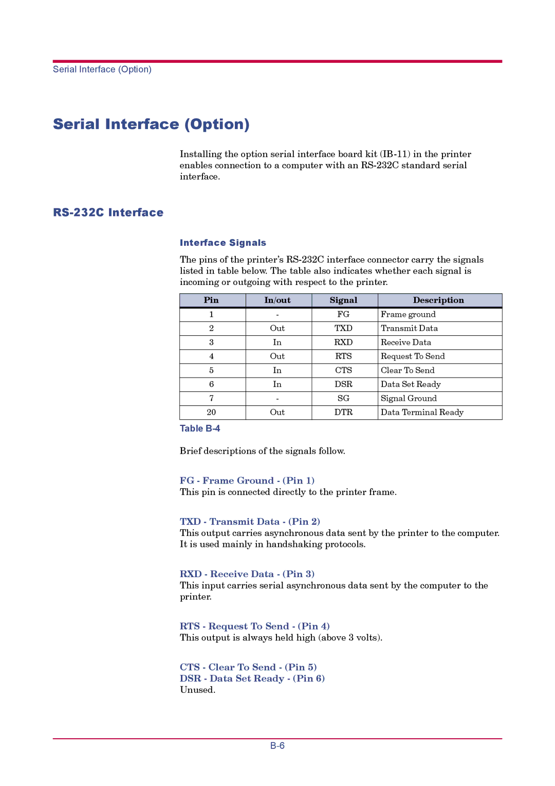
Serial Interface Option
Interface Signals
Pin In/out Signal Description
RS-232C Interface
RS-232C Protocol
Table B-5
Parameter value Baud rate
Table B-6
Table B-7
Parameter value Meaning
Prescribe Frpo D0 Command
Table B-8
Connecting the Printer to the Computer
RS-232C Cable Connection
Obtain a Suitable RS-232C Cable
Double click on Communications Port
RS-232C Cable Connection
DOS, enter the following commands
Appendix C Specifications
Table C-1
Pressure level at the front Dimensions
Power requirements
Power consumption
Description Ambient conditions
Glossary
IEEE1284
Cassette mode
First mode
Dpi dots per inch
Outline font
Sleep mode
Operator panel
Parallel interface
Index
Index-2
Index-3
2003 Is a trademark of Kyocera Corporation