WiPort User Guide
Page
Lantronix Corporate Headquarters
Technical Support
Sales Offices
Disclaimer and Revisions
Contents
Wlan Settings5-19
Contents
Accessing Setup Mode
Expert Settings5-20
Gpio Pins
Factory Defaults
Exit Configuration Mode
Control Protocol
Page
Chapter Summary
Using This Guide
Purpose and Audience
Remaining chapters in this guide include
Using This Guide
Additional Documentation
Introduction
Capabilities
Protocol Support
Configuration Methods
Applications
Introduction
IP Address
Addresses and Port Numbers
Hardware Address
Port Numbers
Page
Configuration using DeviceInstaller
Accessing WiPort using DeviceInstaller
Server Configuration
Wlan Configuration
Host List Configuration
OEM Pin Configuration
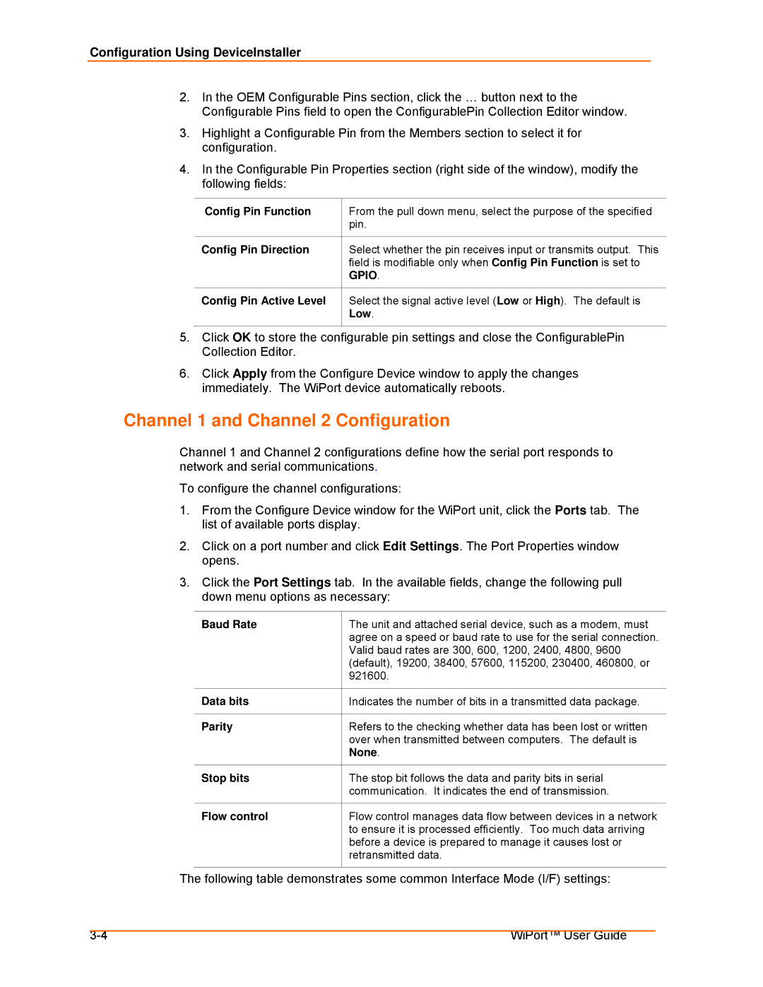
Configuration Using DeviceInstaller
Channel 1 and Channel 2 Configuration
UDP Datagram Mode
Common I/F Mode Setting
Serial Settings
Passive Connection
Active Connection
Disconnection
Connection
Buffer Flushing
Email Configuration
Packing
Triggers
Unit Name
Page
Configuration using Web-Manager
Accessing WiPort using Web-Manager
Network Configuration
Configuration Using Web-Manager
Click the OK button when finished
Automatic IP Address Configuration
Static IP Address Configuration
Select Obtain IP address automatically
IP Address
Select Use the following IP configuration
Default Gateway
Subnet Mask
Server Configuration
Advanced
Serial Settings
Retry Settings
Host Information
Available fields, enter the following information
Port Settings
Disable Serial Port
Channel
Flush Input Buffer Serial to Network
Connection Settings TCP
Pack Control
Flush Output Buffer Network to Serial
Connect Mode Passive Connection
Connect Mode Active Connection
Connect Protocol
Endpoint Configuration
Disconnect Mode
Common Options
Connection Settings UDP
Datagram Mode
Configure the following fields
Change Address Table
Mail Server IP Address
Recipients
Configurable Pins
Enable Serial Trigger
Conditions
Message Properties
Ad Hoc Settings
Wireless Network Security
Enter or modify the following fields
Advanced Settings
Configure or modify the following fields for each pin
Updating Settings
Page
Configuration via Serial Mode or Telnet Port
Accessing Setup Mode
Telnet Access
Serial Port Access
Configuration Via Serial Mode or Telnet Port
Click OK. The following information displays
Set the IP Address
Set the Gateway IP Address
Dhcp Name
Change Telnet Configuration Password
Set the Netmask
Network Class Host Bits Netmask
Mode Option
Interface Mode
Following table displays available I/F Mode options
Interface Mode Options
Port Number
Common I/F Mode Setting Binary Hex
Flow
Flow Control Option
Connect Mode Option
Connect Mode
Enter Connect Mode options in hexadecimal notation
Port Numbers Reserved for
Incoming Connection
Response
Manual Connection
Manual Connection Address Example
Autostart Automatic Connection
Hostlist
Hostlist Example
Modem Mode
Datagram Type
Message Meaning
Modem Mode Command
Modem Mode Commands
Function
Modem Mode Function Command
Remote IP Address
Remote Port
10. Disconnect Mode Options
Flush Mode
Disconnect Mode Option
11. Flush Mode Options
Option
SendChar 1 and SendChar2
DisConnTime Inactivity Timeout
Channel Port Password
Telnet Terminal Type
Mail Server
Recipient
Unit Name
Domain Name
Trigger
Enable Ad Hoc Network Creation
Wlan Settings
Enable Wlan
Find Network Name
Expert Settings
Security Settings
Disable Tftp Firmware Upgrade
Disable Snmp
Disable Telnet Setup
Disable Port 77FE Hex
Factory Defaults
Channel 1 Configuration
Channel 2 Configuration
Wlan Settings
Security Settings
Exit Configuration Mode
Expert Settings
Email Settings
Features
Configurable Pins
Gpio Pins
Control Protocol
Byte 0 Command Types
Commands
Configurable Pins
Command 10h, Get Functions
Command 13h, Get Current States
Command 11h, Get Directions
Command 12h, Get Active Levels
Command 19h, Set Directions
Command details
Command 1Ah, Set Active Levels
Command 1Bh, Set States
Examples
1Bh = response to command 1Bh 03h, 00h, 00h, 00h =
Page
Entering Monitor Mode via the Network Port
Monitor Mode
Entering Monitor Mode via the Serial Port
To enter Monitor Mode locally
Command Command Name Function
Monitor Mode Commands
Following commands are available in Monitor Mode
Monitoring the Network
Obtaining Firmware Reloading Firmware
Using Tftp Graphical User Interface
Updating Firmware
ROM File FWX File
Using Tftp Command Line Interface
Recovering the Firmware Using the Serial Port
Troubleshooting
Troubleshooting
Problems and Error Messages
Problem/Message Reason Solution
Please try again
Caps Lock is not on
General DeviceInstaller Settings
Device Server message
Technical Support
Technical Support Europe, Middle East, and Africa