Return to Section TOC
to Section TOC
Return to Master TOC
to Master TOC
F-53 TROUBLESHOOTING AND REPAIRF-53
MAIN SWITCH BOARD REMOVAL & REPLACEMENT (continued)
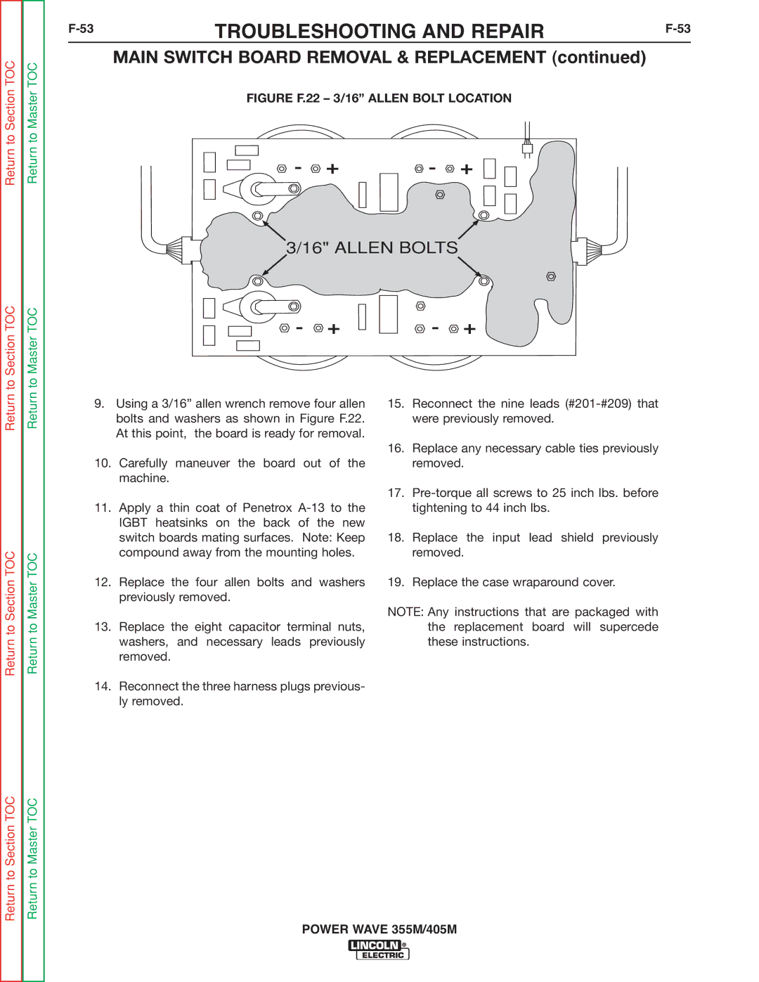
FIGURE F.22 – 3/16” ALLEN BOLT LOCATION
- + | - + |
3/16" ALLEN BOLTS ![]()
![]()
 -
-  +
+ 


 -
-  +
+
Return
Return to Section TOC
Return
Return to Master TOC
9.Using a 3/16” allen wrench remove four allen bolts and washers as shown in Figure F.22. At this point, the board is ready for removal.
10.Carefully maneuver the board out of the machine.
11.Apply a thin coat of Penetrox
12.Replace the four allen bolts and washers previously removed.
13.Replace the eight capacitor terminal nuts, washers, and necessary leads previously removed.
14.Reconnect the three harness plugs previous- ly removed.
15.Reconnect the nine leads
16.Replace any necessary cable ties previously removed.
17.
18.Replace the input lead shield previously removed.
19.Replace the case wraparound cover.
NOTE: Any instructions that are packaged with the replacement board will supercede these instructions.
Return to Section TOC
Return to Master TOC