MAINTENANCE | ||
| VISUAL INSPECTION |
|
![]() WARNING
WARNING
Have qualified personnel do the maintenance work. Always use the greatest care when working near moving parts.
Do not put your hands near the cooling blower fan. If a problem cannot be corrected by following the instructions, take the machine to the nearest Lincoln Field Service Shop.
ELECTRIC SHOCK can kill.
• Do not touch electrically live parts or electrode with skin or wet clothing.
•Insulate yourself from work and ground
•Always wear dry insulating gloves.

 EXPLODING PARTS can cause injury.
• Failed parts can explode or cause other parts to explode when power is applied.
•Always wear a face shield and long sleeves when servicing.
See additional warning information throughout this Manual.
Clean interior of machine with a low pressure air stream. Make a thorough inspection of all compo- nents. Look for signs of overheating, broken leads or other obvious problems. Many problems can be uncovered with a good visual inspection.
ROUTINE MAINTENANCE
1.Every 6 months or so the machine should be cleaned with a low pressure airstream. Keeping the machine clean will result in cooler operation and higher reliability. Be sure to clean these areas:
•All printed circuit boards
•Power switch
•Main transformer
•Input rectifier
•Auxiliary Transformer
•Reconnect Switch Area
•Fan (Blow air through the rear louvers)
2.Examine the sheet metal case for dents or breakage. Repair the case as required. Keep the case in good condition to insure that high voltage parts are protected and correct spacings are maintained. All external sheet metal screws must be in place to insure case strength and electrical ground continuity.
Return to Master TOC
Return to Master TOC
Return to Master TOC
Return to Master TOC
CAPACITOR DISCHARGE PROCEDURE
1.Obtain a power resistor (25 ohms, 25 watts).
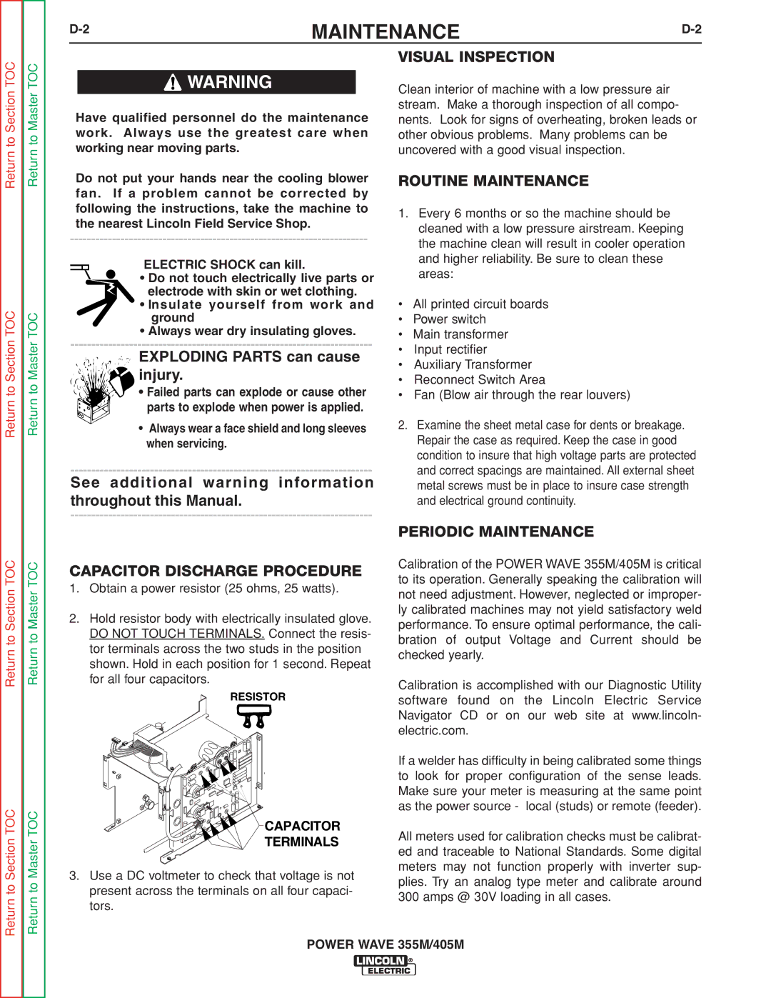
2.Hold resistor body with electrically insulated glove. DO NOT TOUCH TERMINALS. Connect the resis- tor terminals across the two studs in the position shown. Hold in each position for 1 second. Repeat for all four capacitors.
![]() RESISTOR
RESISTOR
CAPACITOR
TERMINALS
3.Use a DC voltmeter to check that voltage is not present across the terminals on all four capaci- tors.
PERIODIC MAINTENANCE
Calibration of the POWER WAVE 355M/405M is critical to its operation. Generally speaking the calibration will not need adjustment. However, neglected or improper- ly calibrated machines may not yield satisfactory weld performance. To ensure optimal performance, the cali- bration of output Voltage and Current should be checked yearly.
Calibration is accomplished with our Diagnostic Utility software found on the Lincoln Electric Service Navigator CD or on our web site at www.lincoln- electric.com.
If a welder has difficulty in being calibrated some things to look for proper configuration of the sense leads. Make sure your meter is measuring at the same point as the power source - local (studs) or remote (feeder).
All meters used for calibration checks must be calibrat- ed and traceable to National Standards. Some digital meters may not function properly with inverter sup- plies. Try an analog type meter and calibrate around 300 amps @ 30V loading in all cases.
Return
POWER WAVE 355M/405M