|
|
|
|
| THEORY OF OPERATION | ||||
Return to Section TOC | Return to Master TOC |
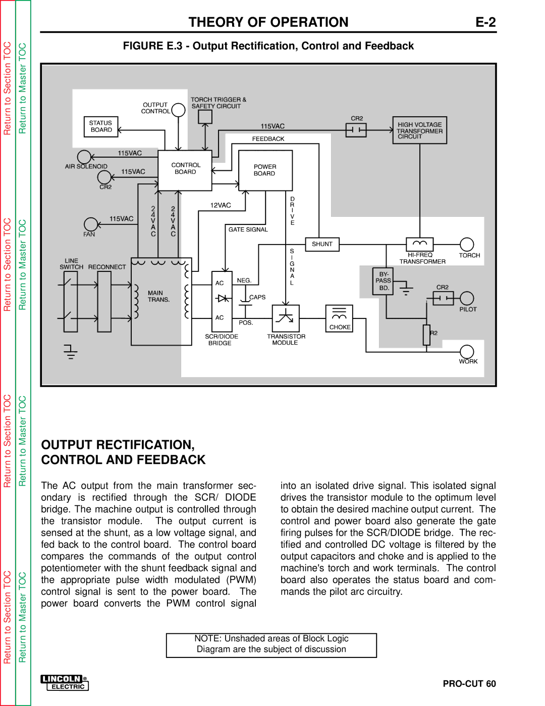
| FIGURE E.3 - Output Rectification, Control and Feedback |
| |||||
|
|
|
|
|
|
| |||
Return to Section TOC | Return to Master TOC |
|
|
|
|
|
|
| |
Section TOC | Master TOC | OUTPUT RECTIFICATION, |
|
|
| ||||
to | to |
|
|
| |||||
CONTROL AND FEEDBACK |
|
|
| ||||||
Return | Return |
|
|
| |||||
The AC output from the main transformer sec- | into an isolated drive signal. This isolated signal | ||||||||
|
| ||||||||
|
| ondary is rectified through the SCR/ DIODE | drives the transistor module to the optimum level | ||||||
|
| bridge. The machine output is controlled through | to obtain the desired machine output current. The | ||||||
|
| the | transistor module. | The | output current is | control and power board also generate the gate | |||
|
| sensed at the shunt, as a low voltage signal, and | firing pulses for the SCR/DIODE bridge. The rec- | ||||||
|
| fed back to the control board. | The control board | tified and controlled DC voltage is filtered by the | |||||
|
| compares the commands of the output control | output capacitors and choke and is applied to the | ||||||
TOC | TOC | potentiometer with the shunt feedback signal and | machine's torch and work terminals. The control | ||||||
the appropriate pulse width modulated (PWM) | board also operates the status board and com- | ||||||||
control signal is sent to the power board. | The | mands the pilot arc circuitry. |
| ||||||
to Section | to Master |
| |||||||
power board converts the PWM control signal |
|
| |||||||
|
|
| NOTE: Unshaded areas of Block Logic |
| |||||
Return | Return |
|
|
|
| ||||
|
|
| Diagram are the subject of discussion |
| |||||
|
|
|
|
|
|
| |||
