|
| TROUBLESHOOTING & REPAIR | ||
TOC | TOC | TORCH, TORCH CABLE ASSEMBLY, INTERNAL TRIGGER, | ||
AND SAFETY CIRCUIT TEST |
| |||
to Section | to Master |
| ||
c. If any of the above tests do not | d. Go to INTERNAL | TRIGGER | ||
Return | Return | agree with the expected normal | AND SAFETY CIRCUIT TEST if | |
|
| |||
|
| resistance specifications, then | all resistance values are within | |
|
| the torch and/or cable must be | the specified range. |
|
|
| repaired or replaced. |
|
|
TOC | TOC |
|
| CONDUCTOR IN GAS TUBE |
|
|
|
| |
| ELECTRODE |
|
|
|
|
| |||
Section | Master |
|
|
|
|
|
| ||
|
|
|
|
| N.C. | CONE |
| ||
|
|
|
|
| SWITCH | ||||
|
|
|
|
| THERMOSTAT | ||||
|
| #336 |
| RED | SAFETY WIRE | ||||
to | to |
| 6J5 | Pin #1 |
|
|
| ||
|
|
|
|
|
| ||||
|
|
|
|
|
|
|
| ||
Return | Return |
|
| #2 |
| BLUE | GUN TRIGGER |
| |
| 3J5 | Pin #2 |
|
|
| ||||
|
|
|
|
|
| ||||
|
| #4 |
| PURPLE |
|
|
| ||
|
|
| 4J5 | Pin #4 |
|
|
| ||
|
| C1 |
|
|
|
| ELECTRODE | ||
|
| 5J5 |
|
|
|
|
| ||
|
|
|
|
|
|
|
| ||
|
|
|
|
|
|
|
|
| |
| VAC | 24 VAC | 7J5 |
|
|
|
|
|
|
|
| #337 |
| WHITE |
|
| NOZZLE | ||
| 24 | #335 | 8J5 | Pin #3 |
|
| |||
|
|
|
|
|
| ||||
|
| #3L | 3J10 |
|
|
|
|
|
|
|
|
|
|
|
|
|
|
| |
|
|
| 6J10 |
| PILOT |
| TORCH HEAD |
| |
Section TOC |
|
|
|
|
|
| |||
Master TOC |
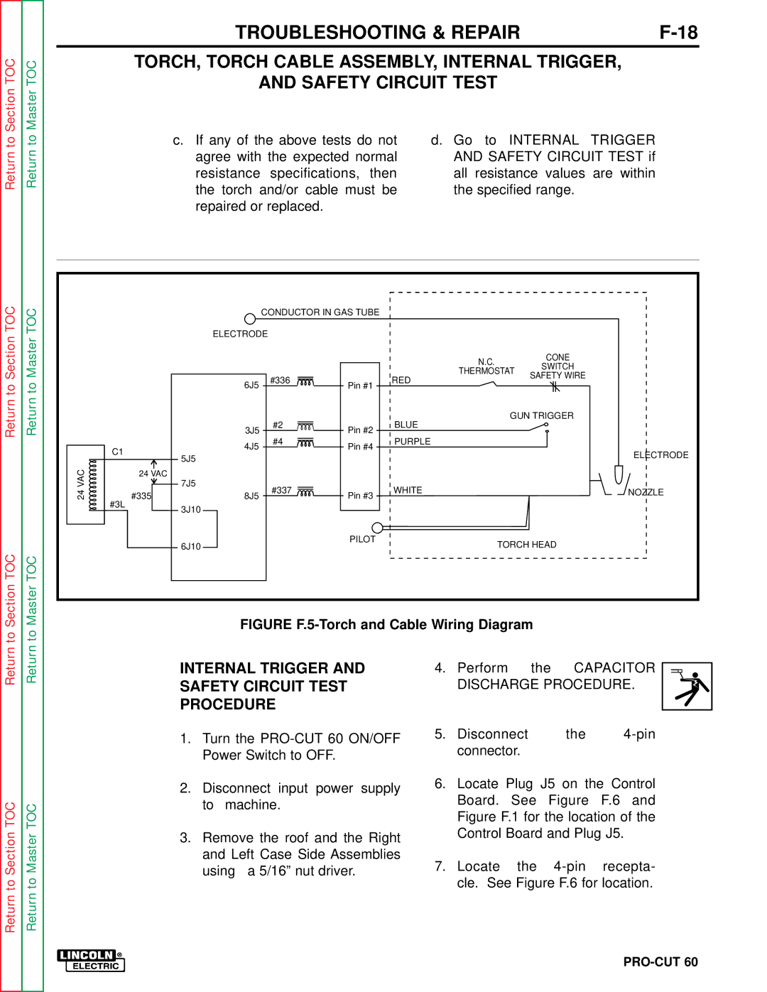
| FIGURE |
| ||||||
to | to |
|
| ||||||
|
|
|
|
|
|
|
| ||
Return | Return |
| INTERNAL TRIGGER AND | 4. | Perform | the | CAPACITOR | ||
| SAFETY CIRCUIT TEST |
|
| DISCHARGE PROCEDURE. | |||||
|
|
|
|
| |||||
|
|
| PROCEDURE |
|
|
|
|
| |
|
| 1. Turn the | 5. | Disconnect | the | ||||
|
|
| connector. |
|
| ||||
|
|
| Power Switch to OFF. |
|
|
|
| ||
|
|
|
|
|
|
|
|
| |
|
| 2. | Disconnect input power | supply | 6. Locate Plug J5 on the Control | ||||
|
|
| Board. | See | Figure | F.6 and | |||
TOC | TOC |
| to machine. |
|
| ||||
|
|
| Figure F.1 for the location of the | ||||||
|
|
|
| ||||||
|
|
|
|
|
| ||||
Section | Master |
| using a 5/16” nut driver. |
| 7. | Control Board and Plug J5. | |||
|
| Locate | the | recepta- | |||||
|
| 3. Remove the roof and the Right |
|
|
|
|
| ||
|
|
| and Left Case Side Assemblies |
|
|
|
|
| |
to | to |
|
|
|
| cle. See Figure F.6 for location. | |||
Return | Return |
|
|
|
|
|
|
|
|