Section TOC
Master TOC
TROUBLESHOOTING & REPAIR |
SCR MODULE REMOVAL
Return to Section TOC
Return to Section TOC
Return to Master TOC
Return to Master TOC
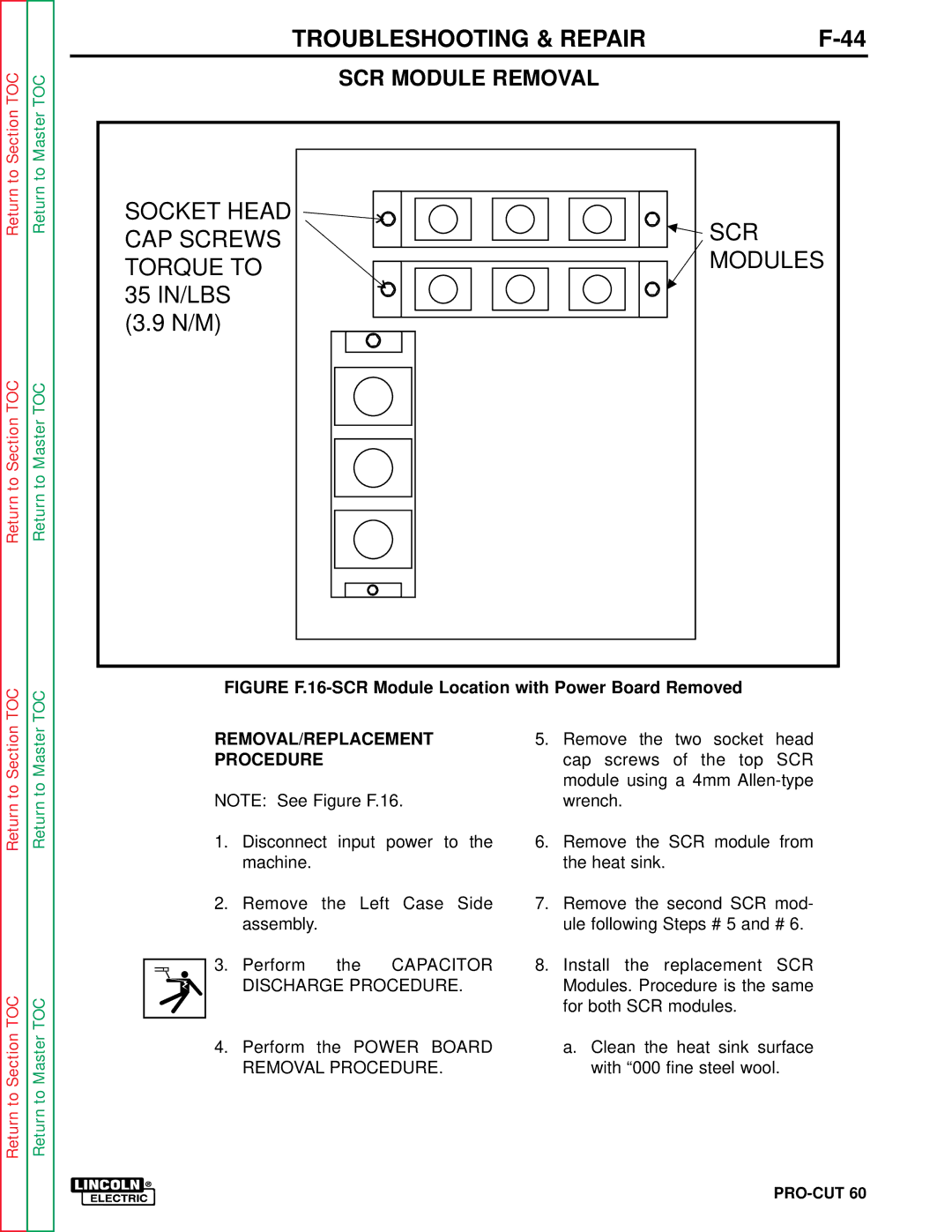
FIGURE F.16-SCR Module Location with Power Board Removed
REMOVAL/REPLACEMENT | 5. | Remove the two socket head | ||
PROCEDURE |
| cap screws of the top SCR | ||
|
|
|
| module using a 4mm |
NOTE: See Figure F.16. |
| wrench. | ||
1. | Disconnect input power to the | 6. | Remove the SCR module from | |
| machine. |
|
| the heat sink. |
2. | Remove the Left Case Side | 7. | Remove the second SCR mod- | |
| assembly. |
| ule following Steps # 5 and # 6. | |
3. | Perform | the CAPACITOR | 8. | Install the replacement SCR |
| DISCHARGE PROCEDURE. |
| Modules. Procedure is the same | |
|
|
|
| for both SCR modules. |
4. | Perform | the POWER BOARD |
| a. Clean the heat sink surface |
| REMOVAL PROCEDURE. |
| with “000 fine steel wool. | |
