Return to Section TOC
Return to Section TOC
Return to Master TOC
Return to Master TOC
TROUBLESHOOTING & REPAIR |
HIGH VOLTAGE TRANSFORMER AND CIRCUIT TEST
➀
➁
➂
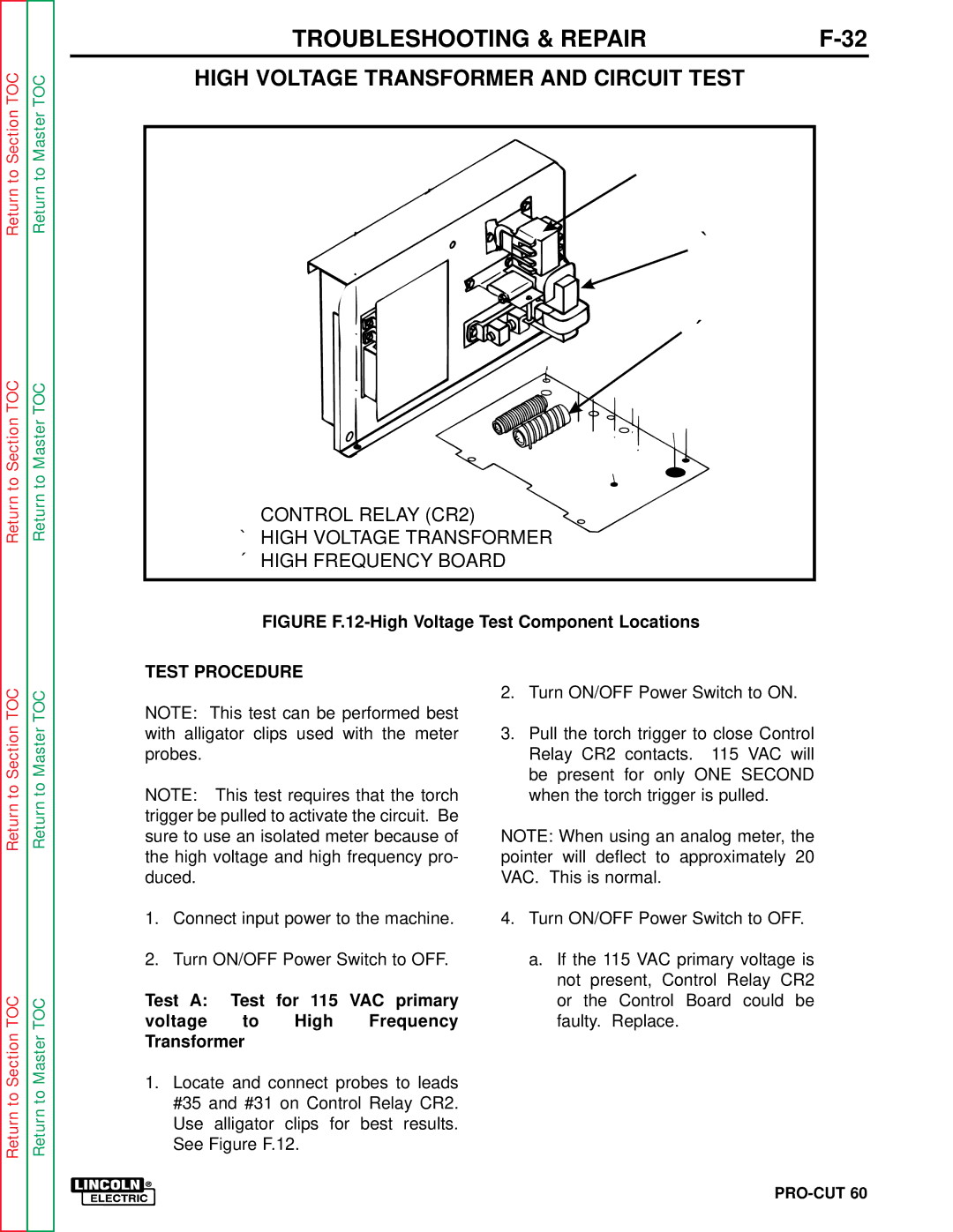
➀CONTROL RELAY (CR2)
➁HIGH VOLTAGE TRANSFORMER
➂HIGH FREQUENCY BOARD
FIGURE F.12-High Voltage Test Component Locations
Return to Section TOC
Return to Section TOC
Return to Master TOC
Return to Master TOC
TEST PROCEDURE
NOTE: This test can be performed best with alligator clips used with the meter probes.
NOTE: This test requires that the torch trigger be pulled to activate the circuit. Be sure to use an isolated meter because of the high voltage and high frequency pro- duced.
1.Connect input power to the machine.
2.Turn ON/OFF Power Switch to OFF.
Test A: Test for 115 VAC primary
voltage to High Frequency Transformer
1.Locate and connect probes to leads #35 and #31 on Control Relay CR2. Use alligator clips for best results. See Figure F.12.
2.Turn ON/OFF Power Switch to ON.
3.Pull the torch trigger to close Control Relay CR2 contacts. 115 VAC will be present for only ONE SECOND when the torch trigger is pulled.
NOTE: When using an analog meter, the pointer will deflect to approximately 20 VAC. This is normal.
4.Turn ON/OFF Power Switch to OFF.
a.If the 115 VAC primary voltage is not present, Control Relay CR2 or the Control Board could be faulty. Replace.