|
| THEORY OF OPERATION | |
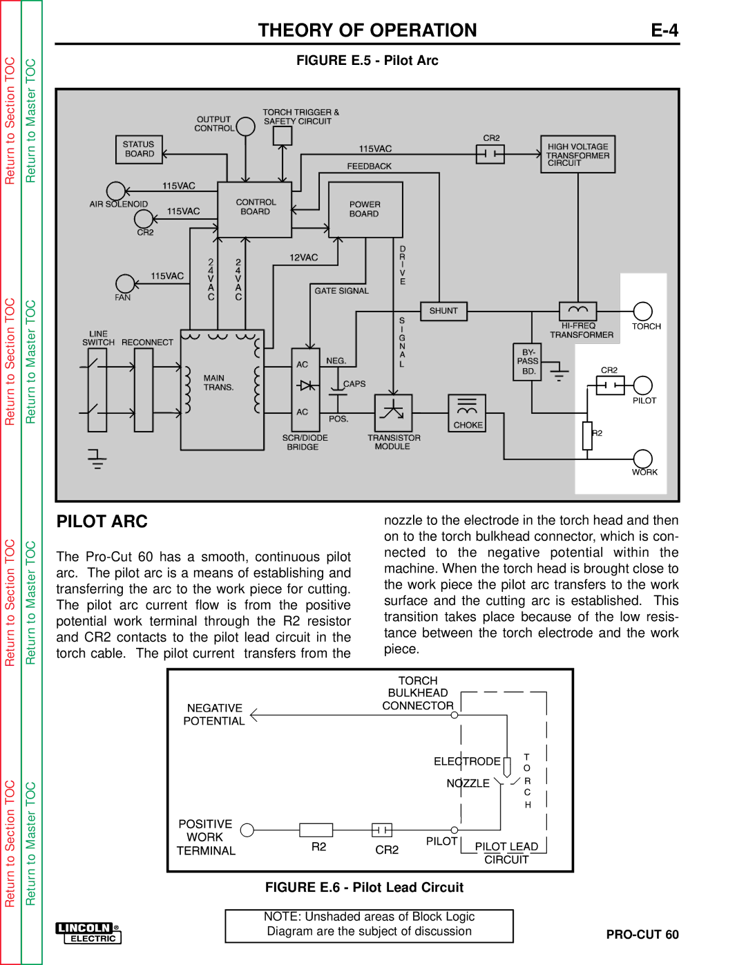
Return to Section TOC | Return to Master TOC | FIGURE E.5 - Pilot Arc |
|
|
| ||
Return to Section TOC | Return to Master TOC |
|
|
|
| PILOT ARC | nozzle to the electrode in the torch head and then | ||
TOC | TOC |
| on to the torch bulkhead connector, which is con- | ||
The | nected to the negative potential within | the | |||
|
| ||||
|
| machine. When the torch head is brought close to | |||
Section | Master | arc. The pilot arc is a means of establishing and | |||
surface and the cutting arc is established. | This | ||||
The pilot arc current flow is from the positive | |||||
|
| transferring the arc to the work piece for cutting. | the work piece the pilot arc transfers to the work | ||
|
|
|
| ||
to | to | potential work terminal through the R2 resistor | transition takes place because of the low resis- | ||
Return | Return | and CR2 contacts to the pilot lead circuit in the | tance between the torch electrode and the work | ||
|
| ||||
|
| piece. |
| ||
|
| torch cable. The pilot current transfers from the |
| ||
|
|
|
| ||
to Section TOC | to Master TOC |
|
|
|
|
|
|
|
|
|
|
|
|
|
|
|
|
|
|
|
| ||
|
|
|
|
|
|
|
|
|
| ||
|
|
|
|
|
|
|
|
|
| ||
|
|
|
|
|
|
|
|
|
| ||
|
|
|
|
|
|
|
|
| |||
|
|
|
|
|
|
|
|
| |||
|
|
|
|
|
|
|
|
| |||
|
|
|
|
|
|
|
|
|
| ||
|
|
|
|
|
|
|
|
|
| ||
|
|
|
|
|
|
|
|
|
| ||
|
|
|
|
|
|
|
|
|
| ||
Return | Return |
|
|
|
|
|
|
|
|
|
|
|
|
|
|
| FIGURE E.6 - Pilot Lead Circuit | ||||||
|
|
|
|
|
|
| |||||
NOTE: Unshaded areas of Block Logic |
|
Diagram are the subject of discussion |
|
