Section TOC
Master TOC
TROUBLESHOOTING & REPAIR |
MAIN TRANSFORMER TEST
Return to
Return to Master TOC
to Master TOC
TEST PROCEDURE
1.Connect main input power supply to machine.
NOTE: When performing Tests A and
B
a.If any one voltage is missing or below the specification, inspect the associated plugs and wiring. If there are no loose plugs or wiring, then the associated winding in the main transformer could be defective. Replace the main transformer.
b.If all secondary and auxiliary voltages are missing, then inspect the Reconnect Panel to make sure the machine is con- nected for the proper operating voltage. If the machine is con- nected properly, the primary winding in the main transformer could be defective. Replace.
Test A: Main Secondary Voltage Test
1.Locate on the Power Board leads H1 and H2 to the SCR module. See Figure F.2.
2.Turn ON/OFF Power Switch to ON.
3.Test for 190 VAC across leads H1 and H2.
4.Turn ON/OFF Power Switch to OFF.
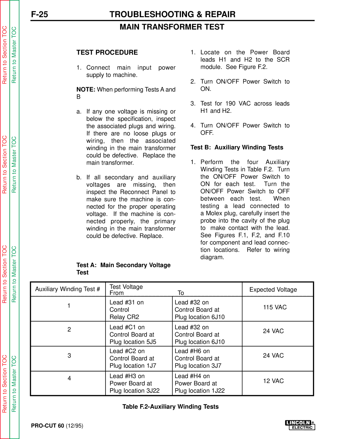
Test B: Auxiliary Winding Tests
1.Perform the four Auxiliary Winding Tests in Table F.2. Turn the ON/OFF Power Switch to
ON for each test. Turn the ON/OFF Power Switch to OFF between each test. When testing a lead connected to a Molex plug, carefully insert the probe into the cavity of the plug to make contact with the lead. See Figures F.1, F.2, and F.10 for component and lead connec- tion locations. Refer to wiring diagram.
Return to
Return to Section TOC
Return
Return to Master TOC
Auxiliary Winding Test # | Test Voltage |
| Expected Voltage | |
From | To | |||
|
| |||
1 | Lead #31 on | Lead #32 on | 115 VAC | |
Control | Control Board at | |||
|
| |||
| Relay CR2 | Plug location 6J10 |
| |
|
|
|
| |
2 | Lead #C1 on | Lead #32 on | 24 VAC | |
Control Board at | Control Board at | |||
|
| |||
| Plug location 5J5 | Plug location 6J10 |
| |
|
|
|
| |
3 | Lead #C2 on | Lead #H6 on | 24 VAC | |
Control Board at | Control Board at | |||
|
| |||
| Plug location 1J7 | Plug location 3J7 |
| |
|
|
|
| |
4 | Lead #H3 on | Lead #H4 on | 12 VAC | |
Power Board at | Power Board at | |||
| ||||
|
| |||
| Plug location 3J22 | Plug location 1J22 |
| |
|
|
|
|
Table