Return to Section TOC
Return to Section TOC
Return to Master TOC
Return to Master TOC
TROUBLESHOOTING & REPAIR |
FAN BLADE AND FAN MOTOR REMOVAL/REPLACEMENT
➀
➁
➂
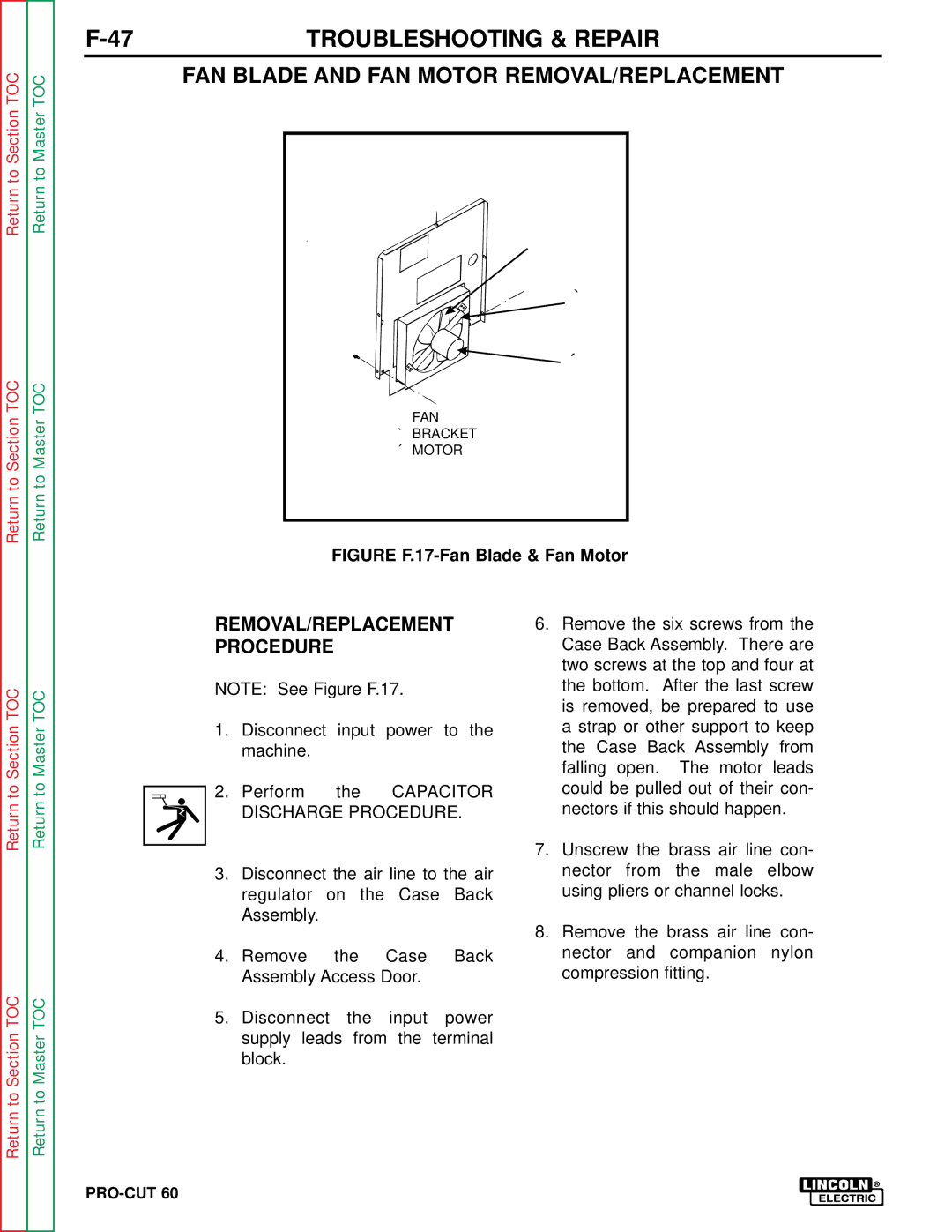
➀FAN
➁BRACKET
➂ MOTOR
FIGURE F.17-Fan Blade & Fan Motor
Return to Section TOC
Return to Section TOC
Return to Master TOC
Return to Master TOC
REMOVAL/REPLACEMENT PROCEDURE
NOTE: See Figure F.17.
1.Disconnect input power to the machine.
2.Perform the CAPACITOR DISCHARGE PROCEDURE.
3.Disconnect the air line to the air regulator on the Case Back Assembly.
4.Remove the Case Back Assembly Access Door.
5.Disconnect the input power supply leads from the terminal block.
6.Remove the six screws from the Case Back Assembly. There are two screws at the top and four at the bottom. After the last screw is removed, be prepared to use a strap or other support to keep the Case Back Assembly from falling open. The motor leads could be pulled out of their con- nectors if this should happen.
7.Unscrew the brass air line con- nector from the male elbow using pliers or channel locks.
8.Remove the brass air line con- nector and companion nylon compression fitting.
