AUTOMATION OUTPUT CONNECTION
✦The Control Panel provides a Automation Output to control lights, devices and appliances.
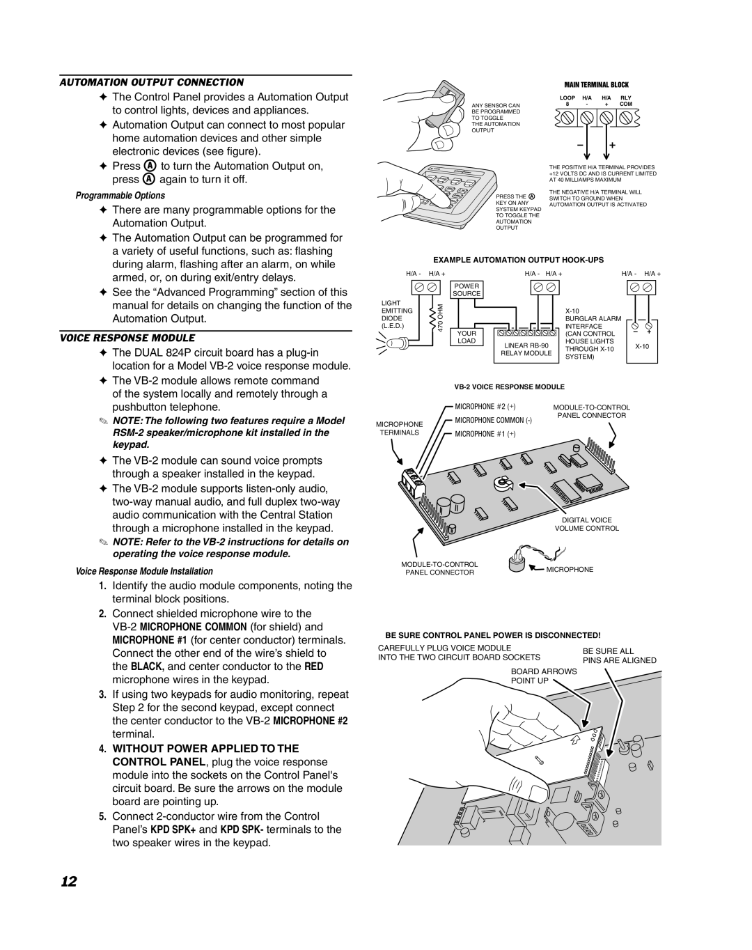
✦Automation Output can connect to most popular home automation devices and other simple electronic devices (see figure).
✦Press ![]() to turn the Automation Output on, press
to turn the Automation Output on, press ![]() again to turn it off.
again to turn it off.
Programmable Options
✦ There are many programmable options for the |
Automation Output. |
✦ The Automation Output can be programmed for |
a variety of useful functions, such as: flashing |
ANY SENSOR CAN
BE PROGRAMMED
TO TOGGLE
THE AUTOMATION
OUTPUT
PRESS THE A
KEY ON ANY
SYSTEM KEYPAD
TO TOGGLE THE
AUTOMATION
OUTPUT
MAIN TERMINAL BLOCK
LOOP | H/A | H/A | RLY | ||||||
8 | - |
| + |
| COM | ||||
|
|
|
|
|
|
|
|
|
|
|
|
|
|
|
|
|
|
|
|
|
|
|
|
|
|
|
|
|
|
THE POSITIVE H/A TERMINAL PROVIDES +12 VOLTS DC AND IS CURRENT LIMITED AT 40 MILLIAMPS MAXIMUM
THE NEGATIVE H/A TERMINAL WILL SWITCH TO GROUND WHEN AUTOMATION OUTPUT IS ACTIVATED
during alarm, flashing after an alarm, on while |
EXAMPLE AUTOMATION OUTPUT
armed, or, on during exit/entry delays. |
✦ See the “Advanced Programming” section of this |
manual for details on changing the function of the |
Automation Output. |
VOICE RESPONSE MODULE
✦ The DUAL 824P circuit board has a |
location for a Model |
✦ The |
H/A -
LIGHT EMITTING DIODE (L.E.D.)
H/A +
![]() 470 OHM
470 OHM
H/A - H/A +
POWER
SOURCE
YOUR |
|
LOAD | LINEAR |
| |
| RELAY MODULE |
H/A - H/A +
BURGLAR ALARM INTERFACE (CAN CONTROL
HOUSE LIGHTS
THROUGH
SYSTEM)
of the system locally and remotely through a |
pushbutton telephone. |
✎NOTE: The following two features require a Model
✦The
✦The
✎NOTE: Refer to the
Voice Response Module Installation
1.Identify the audio module components, noting the terminal block positions.
2.Connect shielded microphone wire to the
3.If using two keypads for audio monitoring, repeat Step 2 for the second keypad, except connect the center conductor to the
4.WITHOUT POWER APPLIED TO THE CONTROL PANEL, plug the voice response module into the sockets on the Control Panel's circuit board. Be sure the arrows on the module board are pointing up.
5.Connect
| ||
| MICROPHONE #2 (+) | |
| MICROPHONE COMMON | PANEL CONNECTOR |
MICROPHONE |
| |
|
| |
TERMINALS | MICROPHONE #1 (+) |
|
DIGITAL VOICE
VOLUME CONTROL
MICROPHONE | ||
PANEL CONNECTOR | ||
|
BE SURE CONTROL PANEL POWER IS DISCONNECTED!
CAREFULLY PLUG VOICE MODULE | BE SURE ALL | |
INTO THE TWO CIRCUIT BOARD SOCKETS | ||
PINS ARE ALIGNED | ||
|
BOARD ARROWS
POINT UP
12