PROGRAM THE HARDWIRED LOOPS
✦Each hardwired loop used must be programmed into the Control Panel's memory.
✦Each hardwired loop programmed uses one of the twenty four available sensor locations.
1.Start with the system in Test Mode (enter the master user code and press TEST).
2.Enter the Setup Mode from Test Mode, enter the master user code then press TEST again.
✴A “Gong” and fi ve “Beeps” will sound. The system is now in Setup Mode.
✴The sensor status indicators will light for any sensors already programmed into the Control Panel.
3.Enter programming Step
4.Press HOME to select step.
5.Enter an unused sensor number from
5 = 05).
6.Press AWAY to store.
✴A single “Bing” tone will sound and the sensor status indicator for that sensor will stay lit. A double “Buzz” will sound if that sensor location is already in use.
7.Repeat Steps 3-6 to enable all of the hardwired loops used.
✎NOTE: The default sensor function for the hardwired loops is Perimeter (Type 5). Any sensor function can be selected for each hardwired loop, refer to the “Customizing the System” section of this manual.
PROGRAM THE WIRELESS SENSORS
✦Each wireless sensor used must be programmed into the system’s memory. See the next two pages for details on activating different models of transmitters.
✦Each wireless sensor programmed uses one of the twenty four available sensor locations.
1.Start with the system in Test Mode (enter any user code and press TEST).
2.Enter the Setup Mode from Test Mode, enter the master user code then press TEST again.
✴A “Gong” and fi ve “Beeps” will sound. The system is now in Setup Mode.
✴The sensor status indicators will light for any sensors programmed into the Control Panel.
3.Enter an unused sensor number from
✴The sensor indicator light will fl ash for the sensor number selected.
4.Activate the sensor by sending a test or alarm signal (be sure the sensor's battery is connected or that its battery protection strip is removed).
✴A single “Bing” tone will sound and the sensor status indicator for that sensor will stay lit. A “Buzz” will sound if that sensor location is already in use.
5.Repeat Steps 3 & 4 for each additional sensor, or exit Setup Mode by pressing the OFF button for three seconds.
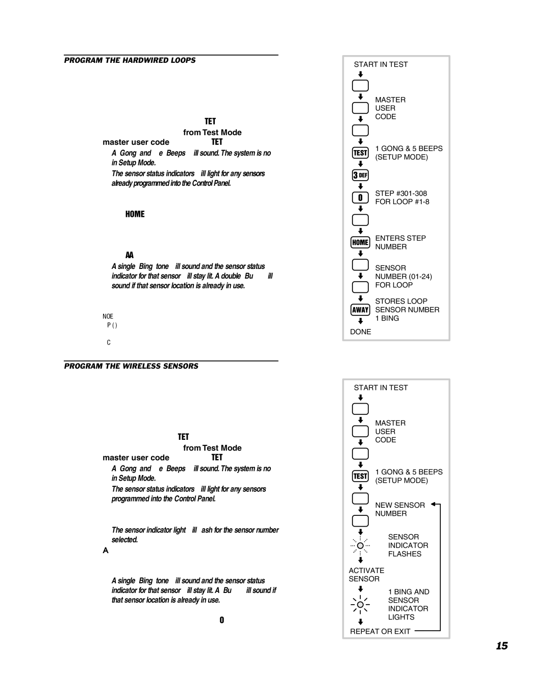
START IN TEST
MASTER
USER
CODE
1 GONG & 5 BEEPS (SETUP MODE)
STEP
FOR LOOP
ENTERS STEP
NUMBER
SENSOR
NUMBER
FOR LOOP
STORES LOOP SENSOR NUMBER 1 BING
DONE
START IN TEST
MASTER
USER
CODE
1 GONG & 5 BEEPS (SETUP MODE)
NEW SENSOR
NUMBER
SENSOR
INDICATOR
FLASHES
ACTIVATE
SENSOR
1 BING AND SENSOR INDICATOR LIGHTS
REPEAT OR EXIT
15