HARDWIRED KEYPAD INSTALLATION
✦One or two Model DUAL 824KP keypads can be used with the DUAL 824P Control Panel (one keypad is included in the DUAL 824 system package).
✦The keypad is supplied with a short wiring harness and connector.
TWIST SCREWDRIVER
IN SLOTS TO OPEN
THE KEYPAD CASE
| KEYPAD |
KEYPAD | SELECT |
JUMPER |
CONNECTOR | SOUNDER (KPD1 OR KPD2) | ||
JUMPER | |||
(ON OR OFF) | |||
MICROPHONE | |||
SPEAKER |
| ||
LOCATION |
| LOCATION | |
|
| ||
| KEYPAD SELECT | |
SOUNDER JUMPER | JUMPER SET | |
TO "KEYPAD 1" | ||
SET TO "ON" | ||
|
DEFAULT JUMPER POSITIONS
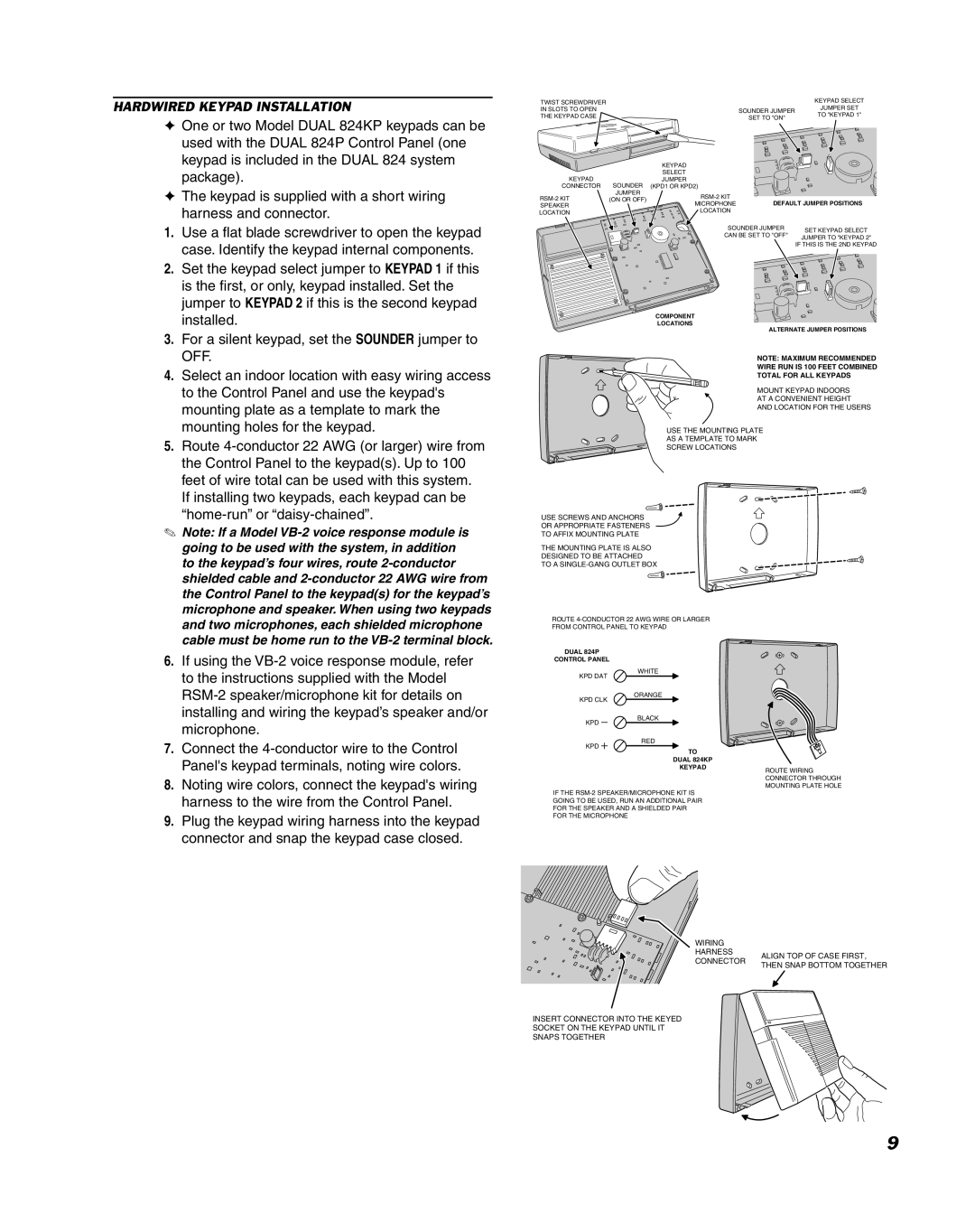
1.Use a flat blade screwdriver to open the keypad case. Identify the keypad internal components.
2.Set the keypad select jumper to KEYPAD 1 if this is the first, or only, keypad installed. Set the jumper to KEYPAD 2 if this is the second keypad installed.
3.For a silent keypad, set the SOUNDER jumper to OFF.
4.Select an indoor location with easy wiring access to the Control Panel and use the keypad's mounting plate as a template to mark the mounting holes for the keypad.
5.Route
✎Note: If a Model
6. If using the |
to the instructions supplied with the Model |
installing and wiring the keypad’s speaker and/or |
SOUNDER JUMPER | SET KEYPAD SELECT | |
CAN BE SET TO "OFF" | ||
JUMPER TO "KEYPAD 2" | ||
| ||
| IF THIS IS THE 2ND KEYPAD |
COMPONENT
LOCATIONS
ALTERNATE JUMPER POSITIONS
NOTE: MAXIMUM RECOMMENDED
WIRE RUN IS 100 FEET COMBINED
TOTAL FOR ALL KEYPADS
MOUNT KEYPAD INDOORS
AT A CONVENIENT HEIGHT
AND LOCATION FOR THE USERS
USE THE MOUNTING PLATE
AS A TEMPLATE TO MARK
SCREW LOCATIONS
USE SCREWS AND ANCHORS
OR APPROPRIATE FASTENERS
TO AFFIX MOUNTING PLATE
THE MOUNTING PLATE IS ALSO
DESIGNED TO BE ATTACHED
TO A
ROUTE
FROM CONTROL PANEL TO KEYPAD
DUAL 824P
CONTROL PANEL
WHITE
KPD DAT
ORANGE
KPD CLK
microphone. |
KPD
BLACK
RED
7. Connect the |
KPD
TO
DUAL 824KP
| Panel's keypad terminals, noting wire colors. |
8. | Noting wire colors, connect the keypad's wiring |
| harness to the wire from the Control Panel. |
9. | Plug the keypad wiring harness into the keypad |
| connector and snap the keypad case closed. |
KEYPAD
IF THE
ROUTE WIRING CONNECTOR THROUGH MOUNTING PLATE HOLE
WIRING |
| |
HARNESS | ALIGN TOP OF CASE FIRST, | |
CONNECTOR | ||
THEN SNAP BOTTOM TOGETHER | ||
|
INSERT CONNECTOR INTO THE KEYED
SOCKET ON THE KEYPAD UNTIL IT
SNAPS TOGETHER
9