Communication | 7193 Owner’s Guide |
Cash Drawer Connectors
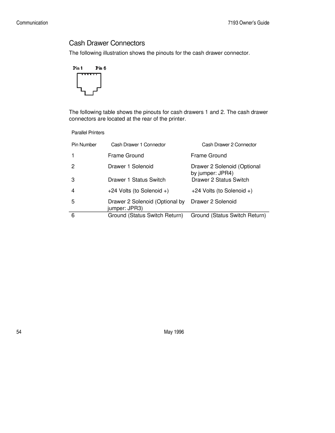
The following illustration shows the pinouts for the cash drawer connector.
Pin 1 | Pin 6 |
|
|
The following table shows the pinouts for cash drawers 1 and 2. The cash drawer connectors are located at the rear of the printer.
Parallel Printers |
|
|
Pin Number | Cash Drawer 1 Connector | Cash Drawer 2 Connector |
1 | Frame Ground | Frame Ground |
2 | Drawer 1 Solenoid | Drawer 2 Solenoid (Optional |
|
| by jumper: JPR4) |
3 | Drawer 1 Status Switch | Drawer 2 Status Switch |
4 | +24 Volts (to Solenoid +) | +24 Volts (to Solenoid +) |
5 | Drawer 2 Solenoid (Optional by | Drawer 2 Solenoid |
| jumper: JPR3) |
|
6 | Ground (Status Switch Return) | Ground (Status Switch Return) |
54 | May 1996 |
