Status Indicators and Control Panel Messages
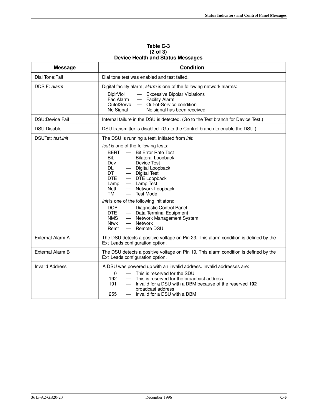
Table C-3
(2 of 3)
Device Health and Status Messages
Message |
|
|
| Condition |
|
| |||
Dial Tone:Fail | Dial tone test was enabled and test failed. | |||
|
| |||
DDS F: alarm | Digital facility alarm; alarm is one of the following network alarms: | |||
| BiplrViol |
| Ð | Excessive Bipolar Violations |
| Fac Alarm | Ð | Facility Alarm | |
| OutofServc | Ð | ||
| No Signal | Ð No signal has been received | ||
|
| |||
DSU:Device Fail | Internal failure in the DSU is detected. (Go to the Test branch for Device Test.) | |||
|
| |||
DSU:Disable | DSU transmitter is disabled. (Go to the Control branch to enable the DSU.) | |||
|
| |||
DSUTst: test,init | The DSU is running a test, initiated from init. | |||
| test is one of the following tests: | |||
| BERT | Ð | Bit Error Rate Test | |
| BiL | Ð | Bilateral Loopback | |
| Dev | Ð | Device Test | |
| DL | Ð | Digital Loopback | |
| DT | Ð | Digital Test | |
| DTE | Ð | DTE Loopback | |
| Lamp | Ð | Lamp Test | |
| NetL | Ð | Network Loopback | |
| TM | Ð | Test Mode | |
| init is one of the following initiators: | |||
| DCP | Ð | Diagnostic Control Panel | |
| DTE | Ð | Data T erminal Equipment | |
| NMS | Ð | Network Management System | |
| Ntwk | Ð | Network | |
| Remt | Ð | Remote DSU | |
|
| |||
External Alarm A | The DSU detects a positive voltage on Pin 23. This alarm condition is defined by the | |||
| Ext Leads configuration option. | |||
|
| |||
External Alarm B | The DSU detects a positive voltage on Pin 19. This alarm condition is defined by the | |||
| Ext Leads configuration option. | |||
|
| |||
Invalid Address | A DSU was powered up with an invalid address. Invalid addresses are: | |||
| 0 | Ð | This is reserved for the SDU | |
| 192 | Ð | This is reserved for the broadcast address | |
| 191 | Ð | Invalid for a DSU with a DBM because of the reserved 192 | |
|
|
| broadcast address | |
| 255 | Ð | Invalid for a DSU with a DBM | |
|
|
|
|
|
December 1996 |
